Cohesive spherical wave generator
A generator and spherical wave technology, applied in the directions of weapon accessories, blasting cylinders, blasting, etc., can solve the problem of poor control of initiation synchronization, and achieve the effects of good loading synchronization, good cohesion effect and simple design.
- Summary
- Abstract
- Description
- Claims
- Application Information
AI Technical Summary
Problems solved by technology
Method used
Image
Examples
Embodiment 1
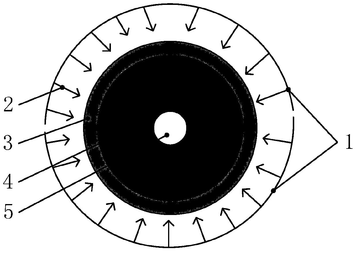
[0030] Such as figure 1 As shown, this embodiment includes a spherical shell-shaped main explosive 4 , a photosensitive explosive coating 3 coated on the outer surface of the spherical shell-shaped main explosive, and a strong light source arranged around the outer surface of the photosensitive explosive coating 3 . The strong light source is an electric explosive device, including a metal wire 1 .
[0031] The metal wire 1 undergoes an electric explosion under the action of a strong current to generate a strong light 2, and the strong light 2 irradiates the photosensitive explosive coating 3 coated on the surface of the spherical shell-shaped main explosive 4, causing the entire surface of the photosensitive explosive coating 3 to explode simultaneously. And generate a detonation wave to detonate the spherical shell-shaped main explosive 4, the detonation wave propagates from the outer surface of the spherical shell-shaped main explosive 4 to the center of the sphere, and sho...
Embodiment 2
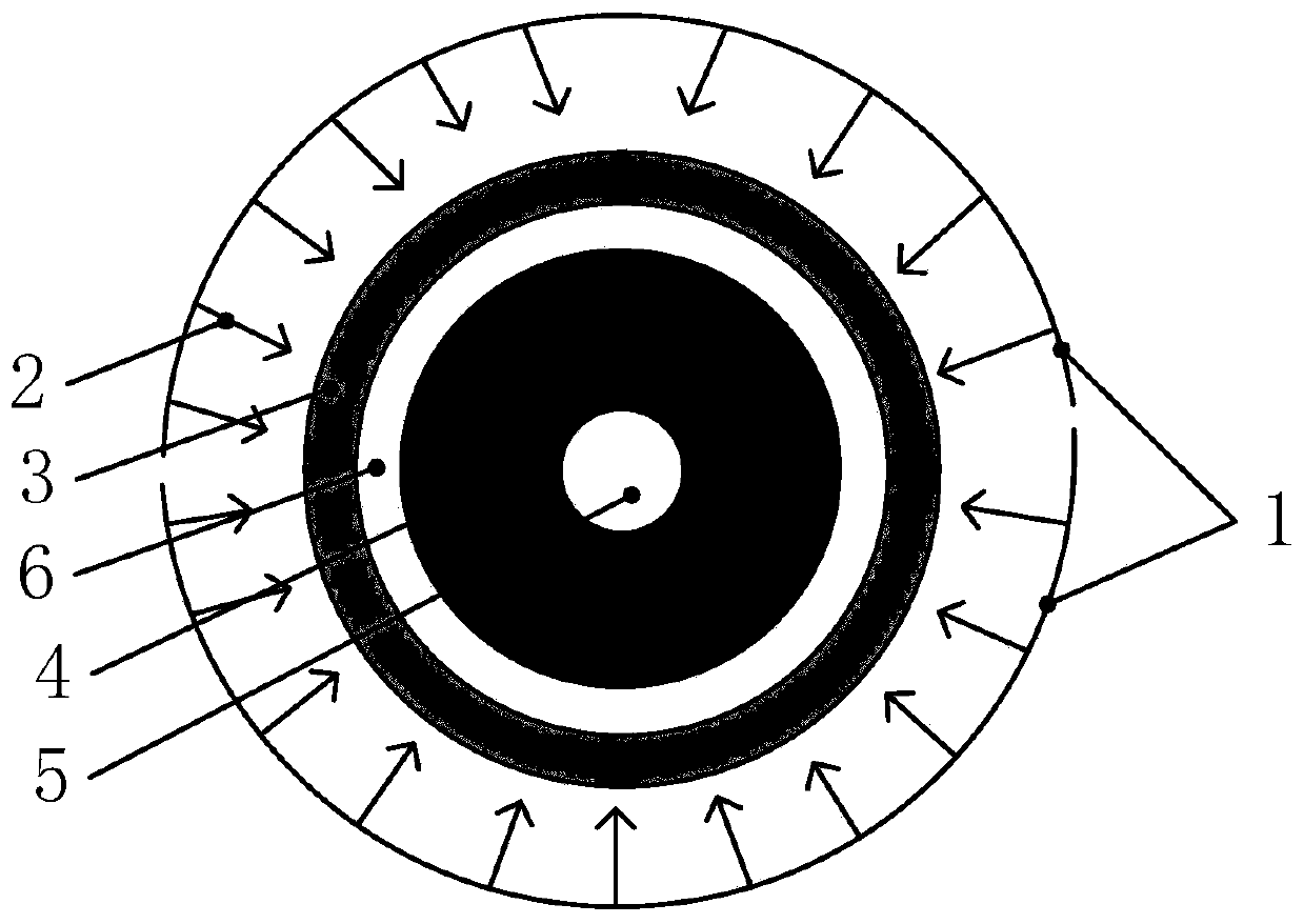
[0033] The difference from Embodiment 1 is that in this embodiment, a metal film / flyer 6 is provided between the spherical shell-shaped main explosive 4 and the photosensitive explosive coating 3 .
[0034] Such as figure 2 As shown, the metal wire 1 undergoes an electric explosion under the action of a strong current to generate a strong light 2, and the strong light 2 irradiates the photosensitive explosive coating 3 coated on the surface of the metal film / flyer 6, so that the entire surface of the photosensitive explosive coating 3 is simultaneously An explosion occurs, and a detonation wave is generated to act on the metal film / flyer 6. Since the metal film / flyer 6 is closely attached to the spherical shell-shaped main explosive 4, the metal film / flyer 6 hits the spherical shell-shaped main explosive 4 to make it Explosion occurs, forming a spherical detonation wave that propagates from the outer surface of the spherical shell-shaped main explosive 4 to the center of the ...
Embodiment 3
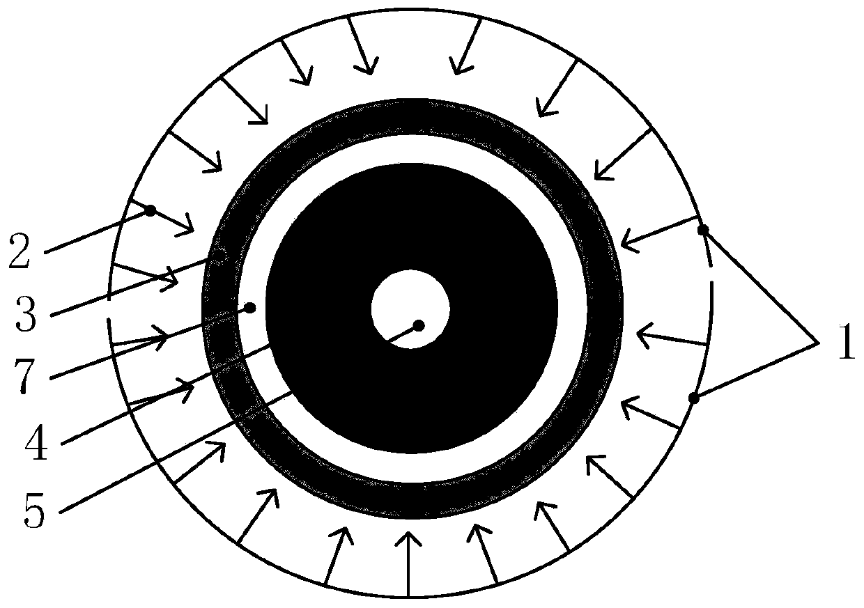
[0036] Different from Embodiment 1, in this embodiment, a booster charge 7 is provided between the spherical shell-shaped main explosive 4 and the photosensitive explosive coating 3 .
[0037] Such as image 3 As shown, the metal wire 1 undergoes an electric explosion under the action of a strong current to generate a strong light 2, and the strong light 2 irradiates the photosensitive explosive coating 3 coated on the surface of the booster 7, so that the entire surface of the photosensitive explosive coating 3 explodes at the same time , and generate a detonation wave to detonate the booster charge 7, the booster charge 7 is in close contact with the spherical shell-shaped main explosive 4, and the detonation wave is transmitted to the spherical shell-shaped main explosive 4 through the booster charge 7 to make it explode, forming a spherical explosion Boom waves propagate from the outer surface of the spherical shell-shaped main explosive 4 to the center of the sphere, and ...
PUM
| Property | Measurement | Unit |
|---|---|---|
| Thickness | aaaaa | aaaaa |
Abstract
Description
Claims
Application Information
 - Generate Ideas
- Intellectual Property
- Life Sciences
- Materials
- Tech Scout
- Unparalleled Data Quality
- Higher Quality Content
- 60% Fewer Hallucinations
Browse by: Latest US Patents, China's latest patents, Technical Efficacy Thesaurus, Application Domain, Technology Topic, Popular Technical Reports.
© 2025 PatSnap. All rights reserved.Legal|Privacy policy|Modern Slavery Act Transparency Statement|Sitemap|About US| Contact US: help@patsnap.com


