One-dimensional planar detonation wave generation device and method for optical detonation
A technology for generating devices and detonation waves, which is used in blasting cylinders, offensive equipment, weapon accessories, etc. to achieve good effects, good loading synchronization, and flexible design.
- Summary
- Abstract
- Description
- Claims
- Application Information
AI Technical Summary
Problems solved by technology
Method used
Image

Examples
Embodiment 1
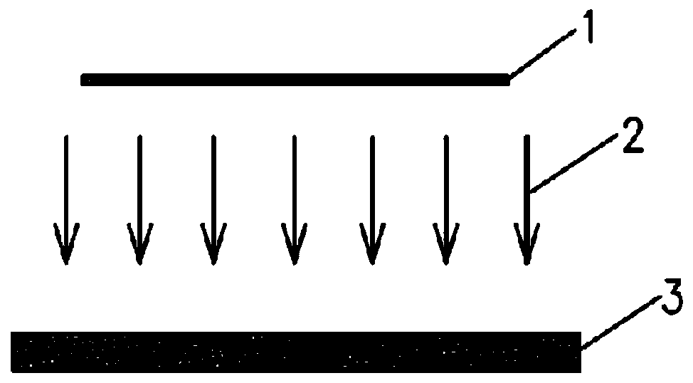
[0042] In this embodiment, the detonating light source is selected as a tungsten wire electric explosion light source. In other embodiments, constantan wire, molybdenum wire or other alloy wires can also be selected; the photosensitive explosive coating is selected from acidic acetylene silver, and its main component is Ag 2 C 2 ·AgNO 3 ;
[0043] figure 1 Among them, the metal wire 1 is a tungsten wire with a diameter of 0.3 mm and a length of 100 mm, and the photosensitive explosive coating 3 is acid acetylene silver with a diameter of 30 mm and a thickness of 0.2 mm. The metal wire 1 undergoes an electric explosion under the action of a strong current to produce strong light 2, and the strong light 2 irradiates the upper surface of the photosensitive explosive coating 3 (the surface on the side of the photosensitive explosive coating opposite to the detonating light source is defined as the upper surface of the photosensitive explosive , The surface opposite to the upper surfac...
Embodiment 2
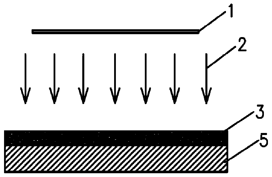
[0045] The difference between this embodiment and the first embodiment is that it also includes a main explosive layer 5. In this embodiment, the main explosive is selected from Tai'an explosives. In other embodiments, other types of solid explosive cartridges or explosive tablets can also be used.
[0046] figure 2 In the first embodiment, the metal wire 1, the strong light 2 and the photosensitive explosive coating 3 are designed according to the first embodiment, and the main explosive layer 5 is a Tai'an explosive with a diameter of 30 mm and a thickness of 2 mm. First, the photosensitive explosive coating 3 is coated on the surface of the main explosive layer 5. The metal wire 1 is electrically exploded under the action of a strong current to produce strong light 2, and the strong light 2 irradiates the photosensitive explosive coating 3 to make the photosensitive explosive coating 3 The surface explodes at the same time, and the plane detonation wave generated by the photos...
Embodiment 3
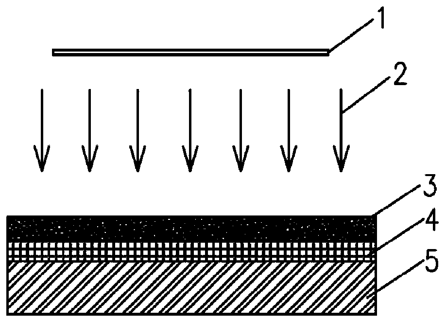
[0048] The difference between this embodiment and the second embodiment is that it also includes a diaphragm. In this embodiment, the diaphragm is made of metal aluminum foil 4, and in other embodiments, metal copper foil can also be used.
[0049] image 3 In the second embodiment, the metal wire 1, the strong light 2, the photosensitive explosive coating 3 and the main explosive layer 5 are designed. First, a layer of metal aluminum foil 4 with a thickness of 0.02mm is pasted on the upper end of the main explosive layer 5, and then the photosensitive explosive coating 3 is coated on the surface of the metal aluminum foil 4. The metal wire 1 undergoes an electric explosion under the action of a strong current to produce strong Light 2, strong light 2 irradiates the photosensitive explosive coating 3, causing the upper surface of the photosensitive explosive coating 3 to explode at the same time. The plane detonation wave generated by the photosensitive explosive coating 3 acts o...
PUM
 Abstract
Description
Claims
Application Information
 - Generate Ideas
- Intellectual Property
- Life Sciences
- Materials
- Tech Scout
- Unparalleled Data Quality
- Higher Quality Content
- 60% Fewer Hallucinations
Browse by: Latest US Patents, China's latest patents, Technical Efficacy Thesaurus, Application Domain, Technology Topic, Popular Technical Reports.
© 2025 PatSnap. All rights reserved.Legal|Privacy policy|Modern Slavery Act Transparency Statement|Sitemap|About US| Contact US: help@patsnap.com