Dynamic derivative test device for pitching and yawing free vibration of aircraft with large slenderness ratio

A test device and large slenderness ratio technology are applied in aerodynamic tests, measuring devices, aircraft component tests, etc., which can solve problems such as complex realization, large internal space of the model, and inability to meet the requirements of wind tunnel tests, etc., and achieve reduction The effect of intermediate connection links, model interference enhancement, and stiffness enhancement

Active Publication Date: 2020-03-31
CHINA ACAD OF AEROSPACE AERODYNAMICS
View PDF10 Cites 2 Cited by
  • Summary
  • Abstract
  • Description
  • Claims
  • Application Information

AI Technical Summary

Problems solved by technology

[0005] Large slenderness ratio aircraft generally refers to aircraft with a slenderness ratio greater than 15, such as air-to-air missiles, rockets, launch vehicles, etc., whose shape characteristics determine the size characteristics of its test model in the wind tunnel. To obtain the dynamic derivative of such aircraft , the traditional form of tail support can no longer meet the requirements of wind tunnel tests
Since the forced vibration test method needs to measure the aerodynamic force and angular displacement of the model at the same time, it needs a large internal space in the front and rear directions of the model, and has strict requirements on the mechanism. For the aircraft with a large slenderness ratio, the forced vibration test method is more complicated to implement

Method used


Image

  • Dynamic derivative test device for pitching and yawing free vibration of aircraft with large slenderness ratio
  • Dynamic derivative test device for pitching and yawing free vibration of aircraft with large slenderness ratio
  • Dynamic derivative test device for pitching and yawing free vibration of aircraft with large slenderness ratio

Examples


Embodiment

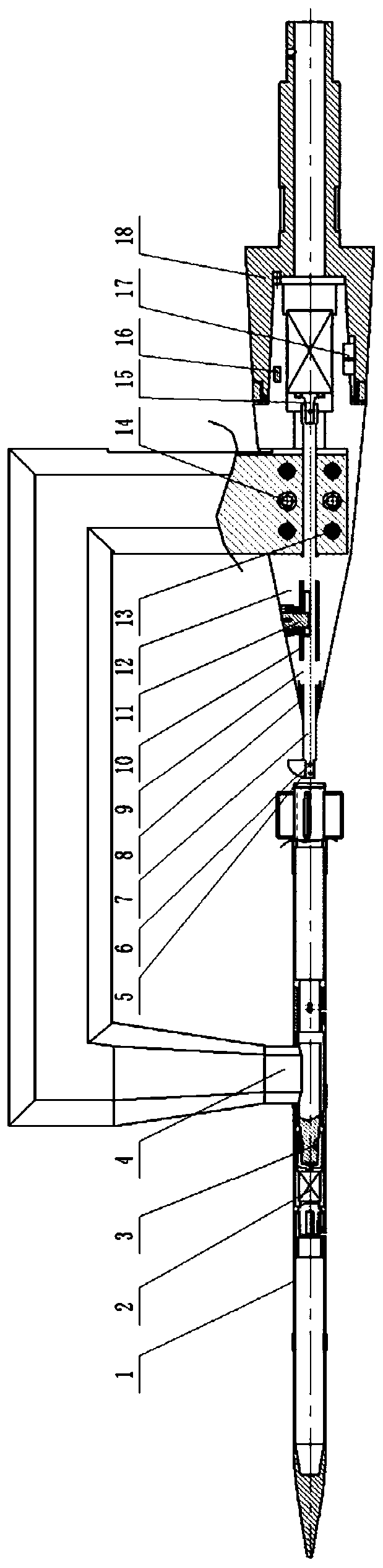
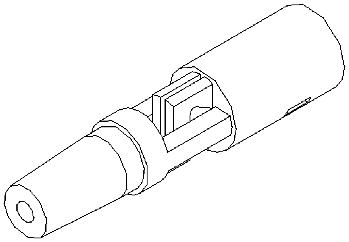
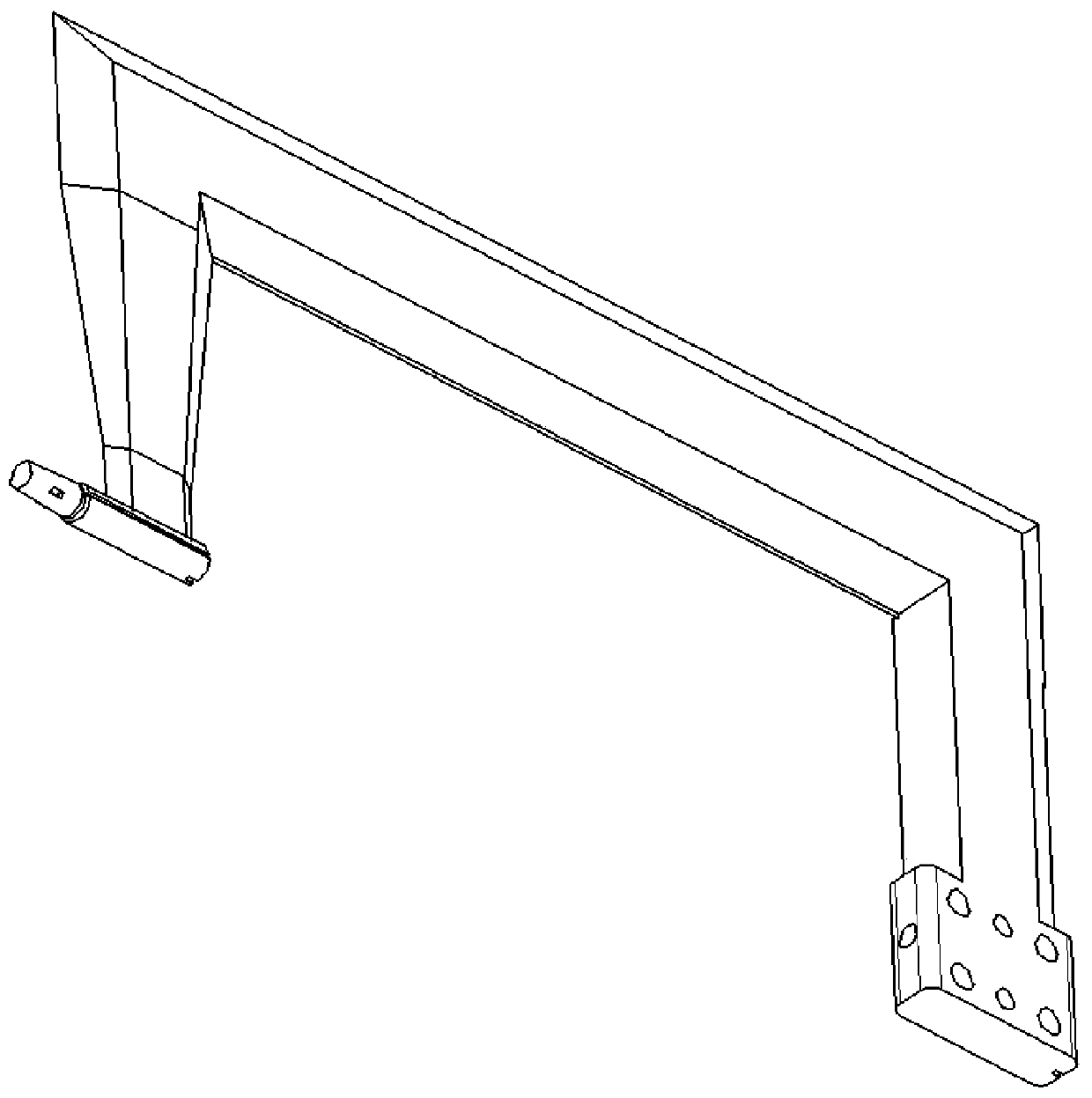
[0053] In the wind tunnel test using the free vibration dynamic derivative test device for the pitch / yaw direction of the large slenderness aircraft of the present invention, the central axis 18 of the device is installed on the wind tunnel scimitar, and the high pressure cylinder 15 is installed on the connecting shaft 8. In the inner cavity, the push rod 7 is driven by the high-pressure cylinder 15 to move quickly back and forth. The driving block on the push rod 7 gives the initial angular displacement of the large slenderness ratio profile model 1. Under the elastic support of the pitch elastic hinge 2, the large slenderness ratio profile model 1 Make free vibration motion around the center of the pitch hinge 2. The time history of angular displacement change can be measured by the strain gauge pasted on the pitch hinge 2, and the pitch dynamic stability derivative can be obtained through corresponding data processing.

[0054] The total length of the entire test mechanism is ...


PUM


Abstract

Disclosed is a dynamic derivative test device for pitching yaw free vibration of an aircraft with a large slenderness ratio. A high-pressure driving device is mounted in a back support device, and anoutput shaft of the high-pressure driving device is connected with the tail end of a push rod (7) in an initial excitation device to drive the push rod (7) to move back and forth; the back support device comprises a back support arm (4), a connecting shaft (12), a back support arm pin (13), a back support arm screw (14), a wedge (16), a positioning key (17) and a middle shaft (18); one end of thepitching elastic hinge (2) is fixedly connected with the back supporting device, and the other end is connected with the large slenderness ratio aircraft test model (1); before and after the test, themovement of the pitching hinge is limited through a push rod (7); and, in the test process, the driving block (5) drives the tail of the model to move upwards through front-back movement of the pushrod, and then the aircraft test model (1) with the large slenderness ratio is driven to do free vibration movement around the rotating center of the pitching elastic hinge (2).

Description

Technical field [0001] The invention relates to a wind tunnel test device which adopts a free vibration dynamic derivative test method to obtain a dynamic derivative in a pitch / yaw direction for an aircraft with a large slenderness ratio profile. Background technique [0002] Both the aerodynamic design and the control system design of the aircraft require the provision of derivative data of the dynamic stability of the aircraft under its flight conditions. When the aircraft changes its attitude or is disturbed by air currents, it will deviate from its balanced attitude in pitch, yaw or roll vibration. The purpose of dynamic stability research is to predict the attenuation trends and laws of these vibrations. For passive damping control aircraft, the dynamic flight quality and reliability requirements of the aircraft put forward extremely high requirements for the prediction of the aircraft dynamic stability. Too low dynamic stability will easily cause the angular movement of t...

Claims


Application Information

Patent Timeline
Patent Type & Authority Applications(China)
IPC IPC(8): G01M9/00G01M9/04B64F5/60
CPCB64F5/60G01M9/00G01M9/04
Inventor 刘金宋玉辉胡静陈兰秦汉王方剑
Owner CHINA ACAD OF AEROSPACE AERODYNAMICS
Why Eureka
Try Eureka