
Composite grinding machining feature automatic identification method based on part engineering image

A processing feature and automatic recognition technology, applied in the field of processing feature recognition and grinding processing feature automatic recognition, can solve the problems of huge application system, difficulty in application expansion, and difficulty in automatic feature recognition, and achieve high pixel-level accuracy and easy portability. Effect

Active Publication Date: 2020-03-31
SHANGHAI UNIV
View PDF4 Cites 5 Cited by
  • Summary
  • Abstract
  • Description
  • Claims
  • Application Information

AI Technical Summary

Problems solved by technology

Graphics applications need to use CAD models to work, and rely on CAD platforms and data exchange standards, such as extracting geometric data from standard formats such as IGES, DXF, and STEP, which are relatively mature and robust, but due to native platform and format constraints, the application The system is huge and application expansion is difficult; image applications have higher flexibility and wider applicable scenarios. At present, some researches are devoted to extracting geometric data from digital images and generating continuous tool paths, but they are only applicable to turning, milling, In the occasions of contour processing such as engraving and wire cutting, a reasonable feature recognition method has not yet been found for complex parts or parts with interlaced features
[0004] Rotary parts are widely used in the manufacturing industry, and the compound grinding center is usually used as a machine tool for the finishing of such complex rotating parts. However, due to its complex shape and the intersecting contours formed by the grinding features of the inner and outer surfaces in the wireframe diagram, automatic feature recognition Difficult, becoming a technical problem to be solved urgently

Method used


Image

  • Composite grinding machining feature automatic identification method based on part engineering image
  • Composite grinding machining feature automatic identification method based on part engineering image
  • Composite grinding machining feature automatic identification method based on part engineering image

Examples


Embodiment Construction

[0050] Below in conjunction with accompanying drawing and specific embodiment above-mentioned scheme is described further, preferred embodiment of the present invention is described in detail as follows:

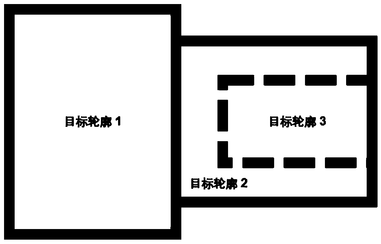
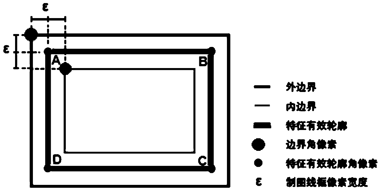
[0051] In this example, see Figure 1-Figure 5 , an automatic recognition method for compound grinding processing features based on part engineering images, including two main steps of geometric contour extraction and process feature matching, wherein according to the image, the geometric contour extraction is divided into external feature contour extraction and internal feature contour extraction. There are two stages, and in the corresponding geometric contour extraction stage, one of the stages meets the input requirements of the geometric contour extraction algorithm through processing, and the interference of the other stage is automatically eliminated; the external feature contour extraction or internal feature contour extraction is achieved through Boundary tracking a...


PUM


Abstract

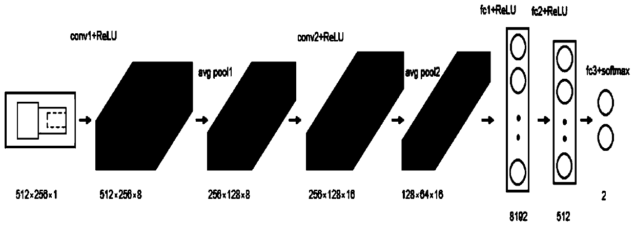
The invention discloses a composite grinding machining feature automatic identification method based on a part engineering image. The method comprises two main body steps of geometric contour extraction and process feature matching. The external features and the internal features are respectively represented by a solid line frame and a dotted line frame, and the geometric contour extraction is divided into two stages, so that the problem of automatic identification of intersection features generally existing in an automatic feature identification technology is solved. The feature geometric contour extraction is based on a boundary tracking algorithm, an effective contour of each feature represented by four angular point pixels is obtained, a CNN classifier is utilized to classify whether internal features exist in a part or not, and finally effective automatic recognition of multiple manufacturing features is sequentially carried out according to geometric information. The method doesnot depend on any CAD tool or data exchange standard, various typical composite grinding machining features can be automatically extracted, high pixel-level precision is guaranteed, and development and application based on the method are lighter and convenient to transplant.

Description

technical field [0001] The invention relates to a processing feature recognition method, in particular to a grinding processing feature automatic recognition method, which is applied in the fields of numerical control machining programming and image technology processing. Background technique [0002] Feature-based NC programming technology is the development trend of NC programming and is called the next generation NC programming technology. This technology mainly includes three key technologies: automatic recognition of processing features, rapid process decision-making and automatic processing of features. The main content of the processing feature recognition technology is to build a processing feature knowledge base based on the solid modeling kernel, and quickly identify the features of the solid models output by CAD software in different formats. The recognition result is a processing feature with engineering significance. This data constitutes CAD and CAPP An intell...

Claims


Application Information

Patent Timeline
Patent Type & Authority Applications(China)
IPC IPC(8): G06K9/62G06K9/46G06T7/00G06T7/12G06T7/13G06N3/04G06N3/08
CPCG06T7/0004G06T7/12G06T7/13G06N3/08G06T2207/20081G06T2207/20084G06T2207/30164G06V10/44G06N3/045G06F18/241Y02P90/30
Inventor 沈南燕赵晨李静吴洋陆宇顺
Owner SHANGHAI UNIV
Learn More