
TOF (Time of Flight)-based optical flow positioning system

A positioning system and optical flow technology, applied in the field of TOF-based optical flow positioning system, can solve the problems of less collected samples, cumulative errors, poor ranging accuracy, etc., to overcome rapid changes in height, fast three-dimensional positioning, high pixel The effect of level precision

Active Publication Date: 2017-10-24
SHANGHAI JIAO TONG UNIV
View PDF8 Cites 14 Cited by
  • Summary
  • Abstract
  • Description
  • Claims
  • Application Information

AI Technical Summary

Problems solved by technology

[0003] 1. The distance measurement accuracy of the ultrasonic ranging module is low, and it is easily disturbed by the external environment such as temperature and wind speed. When the road is rough and the altitude changes rapidly, the ultrasonic ranging can only feedback the height of the central area. The distance measurement accuracy is poor, and the deviation is serious when applied to sound-absorbing materials, resulting in inaccurate optical flow positioning;
[0004] 2. Optical flow calculations mostly use dense optical flow calculations. In order to achieve real-time effects, usually only the optical flow in a small area in the center can be calculated, and the calculated optical flow results and the depth measured by ultrasonic waves are used directly for motion estimation. The collected samples are too large. Less, ignoring the fact that the depth of some areas in the image block does not match the optical flow, it is easy to generate cumulative errors, resulting in drift

Method used


Image

  • TOF (Time of Flight)-based optical flow positioning system
  • TOF (Time of Flight)-based optical flow positioning system
  • TOF (Time of Flight)-based optical flow positioning system

Examples


Embodiment Construction

[0032] The technical solutions proposed by the present invention will be further described in detail below in conjunction with the accompanying drawings and specific embodiments. Advantages and features of the present invention will be apparent from the following description and claims. It should be noted that all the drawings are in very simplified form and use imprecise ratios, which are only used for the purpose of conveniently and clearly assisting in describing the embodiments of the present invention.

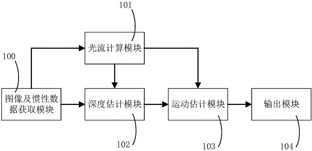
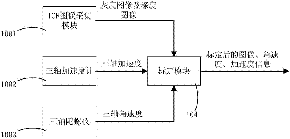
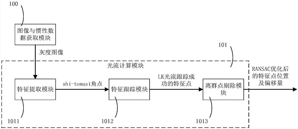
[0033] The present invention is aimed at various problems that may occur in the existing optical flow positioning scheme that uses ultrasonic ranging and camera image acquisition for positioning methods. The TOF camera is applied to the optical flow positioning technology, and the grayscale obtained by the TOF image acquisition module The optical flow calculation module and the depth estimation module are used to obtain the feature point information and depth estimation i...


PUM


Abstract

The invention relates to the field of indoor visual positioning and navigation and in particular relates to a TOF (Time of Flight)-based optical flow positioning system. The system comprises an image and inertia data acquisition module, an optical flow calculation module, a depth estimation module, a motion estimation module and an output module. According to the system disclosed by the invention, the image information as well as acceleration and angular velocity are acquired by the image and inertia data acquisition module, characteristic point information and depth estimation information of the image can be acquired by the optical flow calculation module and the depth estimation module, and then the motion estimation module combines the characteristic point information and depth estimation information and calculates to obtain the final positioning position, so that accurate and rapid three-dimensional positioning is realized.

Description

technical field [0001] The invention relates to the field of indoor visual positioning and navigation, in particular to a TOF-based optical flow positioning system. Background technique [0002] Optical flow positioning is the main positioning method for drones flying indoors. When in use, a camera is usually installed downwards on the bottom of the drone, and the movement of the camera itself is estimated by calculating the movement of pixels in the image, and then passed Calculate the optical flow to get the speed of the camera itself and perform positioning. Most of the current optical flow positioning schemes use a camera and an ultrasonic ranging module, and use the SAD algorithm to calculate the optical flow. This optical flow positioning scheme has the following defects: [0003] 1. The distance measurement accuracy of the ultrasonic ranging module is low, and it is easily disturbed by the external environment such as temperature and wind speed. When the road is roug...

Claims


Application Information

Patent Timeline
Patent Type & Authority Applications(China)
IPC IPC(8): G01C11/00G01C11/12G06T7/521G06T7/246
CPCG01C11/00G01C11/12G06T7/246G06T7/521G06T2207/10016G06T2207/10052
Inventor 钱久超王兆圣刘佩林郁文贤慕翔洪燕
Owner SHANGHAI JIAO TONG UNIV
Learn More