
Image sharpening method and device

An image sharpening and image technology, applied in the field of image sharpening, can solve the problems of noise amplification, uncontrolled thickness, halo effect and overshoot problem reduction, etc., to suppress noise sharpening and efficient sharpening operations. , the effect of meeting changes and needs

Active Publication Date: 2020-03-31
SHANGHAI FULLHAN MICROELECTRONICS
View PDF9 Cites 0 Cited by
  • Summary
  • Abstract
  • Description
  • Claims
  • Application Information

AI Technical Summary

Problems solved by technology

[0003] The Chinese patent application with the publication number CN103079038A proposes an image sharpening processing method. The patent mentions that the traditional method will cause noise amplification, but it does not essentially distinguish the noise in the flat area of ​​​​the image from the texture area of ​​​​the image boundary. Then only sharpen the details of the image boundary texture area to suppress the noise amplification problem in the flat area; the Chinese patent application with the publication number CN103514583A also proposes an image sharpening method, which mentions that the traditional method will produce a halo effect on black and white edges , the above-mentioned Chinese patent application with publication number CN103079038A also mentioned the overshoot problem on the boundary of the traditional method, but none of them essentially controlled the thickness of the image boundary sharpening, only sharpened the boundary information after thinning, so the halo effect and The problem of overshoot will be greatly reduced

Method used


Image

  • Image sharpening method and device
  • Image sharpening method and device
  • Image sharpening method and device

Examples


Embodiment

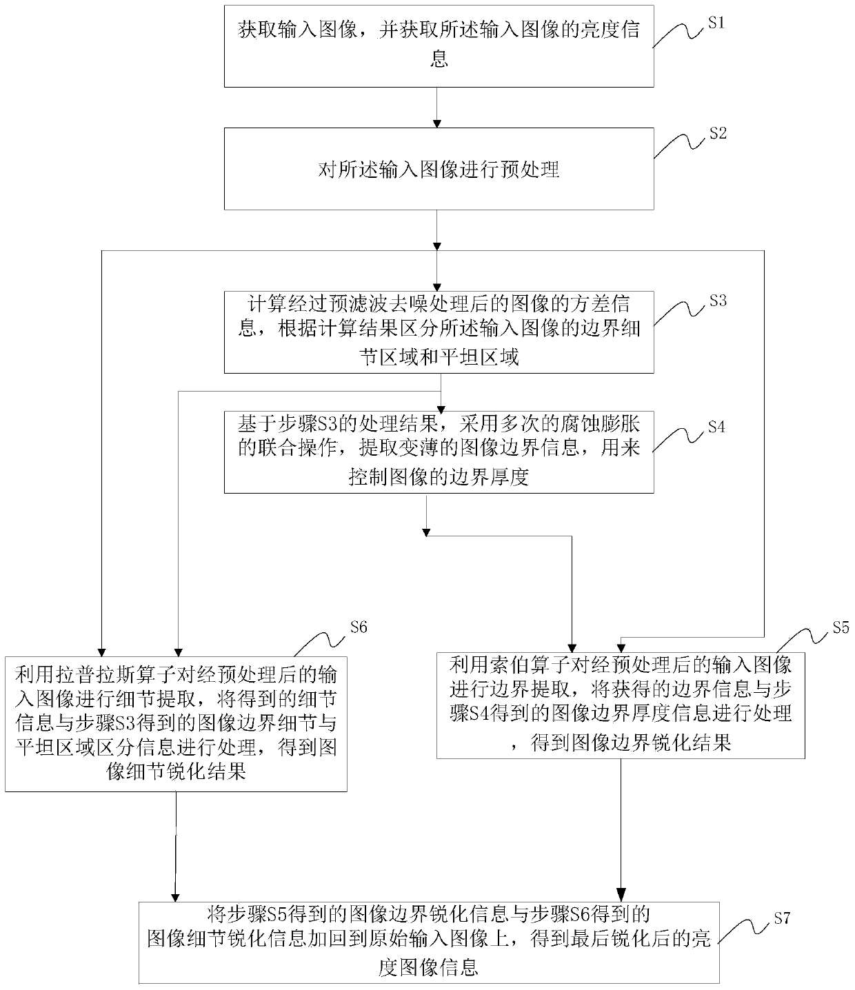
[0089] Such as Figure 6As shown, in this embodiment, the image sharpening device of the present invention includes:

[0090] The image acquiring unit 201 is configured to acquire brightness information of an input image, for sending the image brightness information to a subsequent unit.

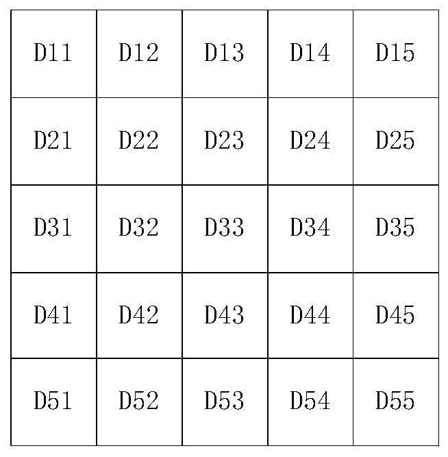
[0091] The image preprocessing unit 202, this unit can reduce the noise of the flat area to the greatest extent while retaining the boundary detail information of the image by using 1×5 window processing, and the calculation formula is shown in formula (1).

[0092] The image boundary detail and flat area distinguishing unit 203, this unit uses a 3×3 window to calculate the variance information of each point, and the variance can further reduce the noise of the flat area while retaining the image boundary detail information. The calculation formula is as the formula ( 2) as shown.

[0093] The first-level expansion operation unit 204, this unit uses the first-level expansion operation to c...


PUM


Abstract

The invention discloses an image sharpening method and device. The method comprises the steps of S1, obtaining an input image and brightness information thereof; s2, carrying out image preprocessing;s3, calculating variance information of the preprocessed image, and distinguishing a boundary detail area and a flat area of the image; s4, extracting thinned image boundary information by adopting multiple corrosion expansion joint operations; s5, performing boundary extraction on the preprocessed image, and processing the obtained boundary information and image boundary thickness information toobtain an image boundary sharpening result; s6, performing detail extraction on the preprocessed input image, and processing the obtained detail information and the image boundary detail and flat region distinguishing information obtained in the step S3 to obtain an image detail sharpening result; and S7, adding the image boundary sharpening information and the image detail sharpening informationback to the original input image to obtain final sharpened brightness image information.

Description

technical field [0001] The present invention relates to the technical field of video image processing, in particular to an image sharpening method and device. Background technique [0002] The currently commonly used image sharpening method is to extract the middle and low frequency boundary information and high frequency detail information of the image, and then add the boundary information and detail information back to the original image to obtain the sharpened image. The key issue of image sharpening is how to only sharpen the information in the texture area of ​​the image boundary and balance the noise suppression in the flat area. [0003] The Chinese patent application with the publication number CN103079038A proposes an image sharpening processing method. The patent mentions that the traditional method will cause noise amplification, but it does not essentially distinguish the noise in the flat area of ​​​​the image from the texture area of ​​​​the image boundary. T...

Claims


Application Information

Patent Timeline
Patent Type & Authority Applications(China)
IPC IPC(8): G06T5/00G06T7/13G06T7/155G06T7/168
CPCG06T7/13G06T7/155G06T7/168G06T5/73G06T5/70
Inventor 詹进朱媛媛刘学彦陈佳男罗敏之
Owner SHANGHAI FULLHAN MICROELECTRONICS
Learn More