
Audio equipment and rear cavity structure thereof

An audio equipment and rear cavity technology, which is applied in the field of electronic equipment, can solve the problems of reducing the compliance Cms of the vibration system, reducing the compliance of speakers, and deteriorating low-frequency performance.

Pending Publication Date: 2020-03-31
GEER TECH CO LTD
View PDF0 Cites 0 Cited by
  • Summary
  • Abstract
  • Description
  • Claims
  • Application Information

AI Technical Summary

Problems solved by technology

At present, for some audio devices with high waterproof requirements (such as smart bracelets, etc.), due to their small size, the speakers can only adopt a closed box design, and cannot open holes to improve low-frequency performance
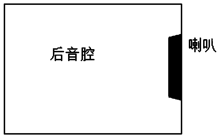
[0003] The existing closed box design is to directly install the loudspeaker in a closed rear sound cavity (such as figure 1 shown), in order to facilitate waterproof sealing, where the resonant frequency relation is Mms is the equivalent mass of the speaker, and the resonance frequency of the speaker is F0. After the speaker is added to the rear cavity, due to the influence of the additional compliance of the cavity, the equivalent parallel compliance Cms=V / (1.4*10 5 ), V is the volume of the back cavity. Since the back cavity is closed and the volume is small, it is equivalent to greatly reducing the compliance of the speaker, reducing the compliance Cms of the entire vibration system, and the resonance frequency becomes F1, F0<F1, so the low frequency The higher the resonance frequency, the worse the low frequency performance

Method used


Image

  • Audio equipment and rear cavity structure thereof
  • Audio equipment and rear cavity structure thereof
  • Audio equipment and rear cavity structure thereof

Examples


Embodiment Construction

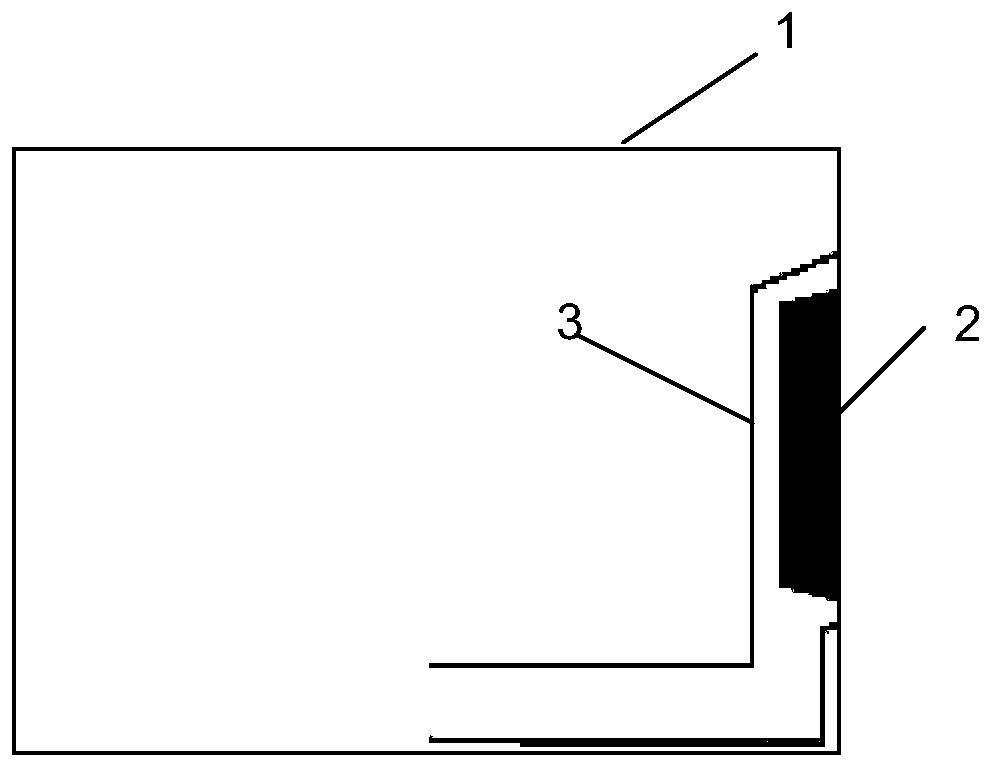
[0024] Embodiments of the present invention provide an audio device and its rear cavity structure, which can reduce the resonance frequency during use and improve the low-frequency performance of the product.

[0025] In order to make the purpose, technical solutions and advantages of the embodiments of the present invention clearer, the technical solutions in the embodiments of the present invention will be clearly and completely described below in conjunction with the drawings in the embodiments of the present invention. Obviously, the described embodiments It is a part of embodiments of the present invention, but not all embodiments. Based on the embodiments of the present invention, all other embodiments obtained by persons of ordinary skill in the art without making creative efforts belong to the protection scope of the present invention.

[0026] Please refer to figure 2 , figure 2 It is a schematic structural diagram of a rear chamber structure of an audio device pr...


PUM


Abstract

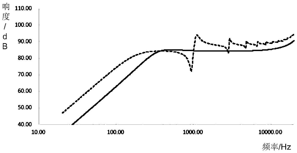
The invention discloses audio equipment and a rear cavity structure thereof, the audio equipment comprises a rear cavity shell, a horn arranged on the inner wall of the rear cavity shell and a guide pipe arranged in the rear cavity shell, the first end of the guide pipe is arranged around the horn and attached to the inner wall so as to wrap the horn in the guide pipe, and the second end of the guide pipe extends into the cavity of the rear cavity shell; according to the invention, the guide pipe is added in the rear cavity; and the first end of the guide pipe wraps the horn in the guide pipe,the second end of the guide pipe extends into the cavity of the rear cavity shell, and air in the guide pipe vibrates along with the vibration of the diaphragm in the vibration process of the diaphragm of the horn, so that the additional vibration mass is increased, the overall mass of the rear cavity is increased, the resonance frequency is reduced, and the low-frequency performance is improved.

Description

technical field [0001] The embodiments of the present invention relate to the technical field of electronic equipment, and in particular, to an audio equipment and its rear cavity structure. Background technique [0002] With the continuous improvement of people's requirements for electronic products, portable and miniaturized electronic products are more and more favored by people. At present, for some audio devices with high waterproof requirements (such as smart bracelets, etc.), due to their small size, the speakers can only adopt a closed box design, and cannot open holes to improve low-frequency performance. [0003] The existing closed box design is to directly install the loudspeaker in a closed rear sound cavity (such as figure 1 shown), in order to facilitate waterproof sealing, where the resonant frequency relation is Mms is the equivalent mass of the speaker, and the resonance frequency of the speaker is F0. After the speaker is added to the rear cavity, due t...

Claims


Application Information

Patent Timeline
IPC IPC(8): H04R1/02
CPCH04R1/02H04R2201/02
Inventor 铁广朋张喜乐
Owner GEER TECH CO LTD
Learn More