Supercharge Your Innovation With Domain-Expert AI Agents!

Toilet cleaning brush

A cleaning brush and toilet technology, applied in the field of sanitary ware, can solve the problems of low cleaning power, long drying time, difficult to remove dirt, etc., and achieve the effect of high cleaning power and convenient operation

Inactive Publication Date: 2020-04-03
吉村信一郎
View PDF8 Cites 0 Cited by
  • Summary
  • Abstract
  • Description
  • Claims
  • Application Information

AI Technical Summary

Problems solved by technology

[0002] Existing toilet brushes are generally divided into brush-type toilet brushes and sponge-type toilet brushes; the brush-type toilet brushes have a wider brushing surface, but due to the gaps between the bristles, small ordinary dirt will be missed; the cleaning power is low; as in the Chinese patent application No. CN201420847.31.6, the announcement date is: 2015.05.20, which discloses a cleaning brush, which specifically includes a handle, a brush rod and a brush head. The brush rod is supported by a stainless steel spiral tube, one end of which is fixedly connected to the handle, and the other end It is fixedly connected with the brush head, and the brush head is surrounded by bristle bundles. The longitudinal section of the bristle bundle is butterfly-shaped. There are no bristles, and when the area to be cleaned is small, the bristles cannot be adjusted according to the actual situation for cleaning, resulting in low cleaning power. At the same time, the bristles rebound and splash water easily during cleaning, and there is capillary phenomenon, causing water to accumulate between the bristles; sponge type The toilet brush will not splash water when used, but the sponge is relatively soft, and it is difficult to remove stubborn dirt; at the same time, the sponge absorbs more water and takes a long time to dry, which is easy to breed bacteria and has hygienic problems

Method used


Image

  • Toilet cleaning brush
  • Toilet cleaning brush
  • Toilet cleaning brush

Examples


Embodiment 1

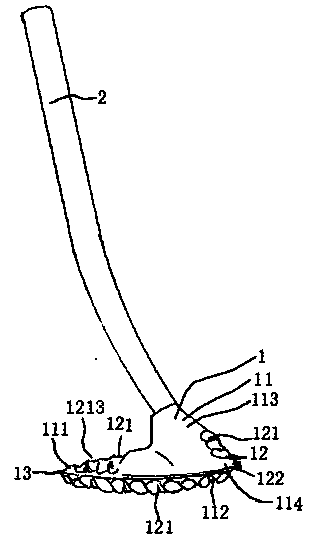
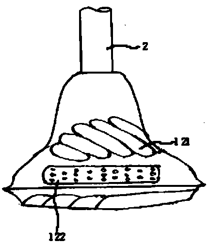
[0046] Such as Figure 1-5 , Figure 15-17 As shown, a toilet cleaning brush includes a brush head 1 and a handle 2; the brush head 1 includes a cleaning part 11 and a cleaning part 12.

[0047]The cleaning section 11 is a shoe-shaped cleaning section. The cleaning part 12 comprises a first cleaning part 121 and a second cleaning part 122; the cleaning part 11 comprises a first cleaning part 111, a second cleaning part 112, a third cleaning part 113 and a fourth cleaning part 114; the second cleaning part 112 is located at The bottom of the brush head 1, the first cleaning part 111 is located at the front side of the top of the brush head 1, the third cleaning part 113 is located at the rear side of the top of the brush head 1, and the fourth cleaning part 114 is located below the third cleaning part 113; The cleaning parts 121 are arranged on the surfaces of the first cleaning part 111, the second cleaning part 112 and the third cleaning part 113, and there are more than tw...

Embodiment 2

[0068] Such as figure 1 , 2 , 7-9, and 15-17, a toilet cleaning brush includes a brush head 1 and a handle 2; the brush head 1 includes a cleaning part 11 and a cleaning part 12.

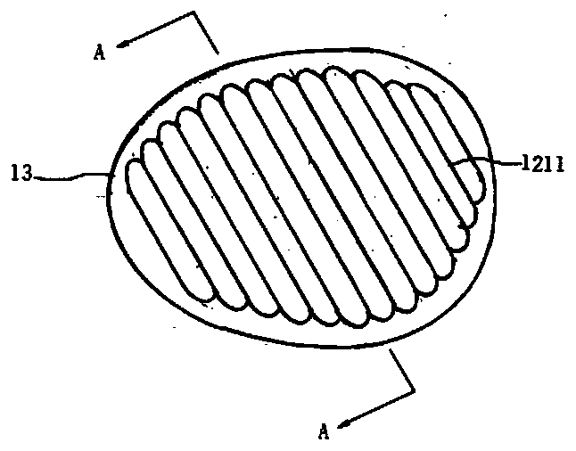
[0069] The cleaning section 11 is a shoe-shaped cleaning section. The cleaning part 12 includes a first cleaning part 121 and a second cleaning part 122; the cleaning part 11 includes a first cleaning part 111, a second cleaning part 112 and a third cleaning part 113; the second cleaning part 112 is located at the bottom of the brush head 1, The first cleaning part 111 is positioned at the front side of the top of the brush head 1, the third cleaning part 113 is positioned at the rear side of the top of the brush head 1, and the first cleaning part 121 is arranged on the first cleaning part 111, the second cleaning part 112 and the third cleaning part 111. On the surface of the cleaning part 113, there are more than two first cleaning parts 121. The first cleaning part 121 is formed with an inward...

Embodiment 3

[0091] Such as Figure 6-9 , 17, a toilet cleaning brush, including a brush head 1 and a handle 2;

[0092]The cleaning section 11 is a shoe-shaped cleaning section. The cleaning part 12 comprises the first cleaning part 121; the cleaning part 11 comprises the first cleaning part 111, the second cleaning part 112, the third cleaning part 113 and the fourth cleaning part (not shown); the second cleaning part 112 is located at The bottom of the brush head 1, the first cleaning part 111 is located at the front side of the top of the brush head 1, the third cleaning part 113 is located at the rear side of the top of the brush head 1, and the fourth cleaning part is located below the third cleaning part 113; the first cleaning Parts 121 are arranged on the surface of the first cleaning part 111, the second cleaning part 112 and the third cleaning part 113, the first cleaning part 121 is provided with more than two, and the first cleaning part 121 is formed with an inwardly recesse...


PUM


Abstract

The invention provides a toilet cleaning brush. The toilet cleaning brush comprises a brush head and a handle, the cleaning brush is characterized in that the brush head comprises a cleaning part anda cleaning piece, and the cleaning piece comprises first cleaning pieces; the cleaning part comprises a first cleaning part, a second cleaning part, a third cleaning part and a fourth cleaning part; the first cleaning pieces are arranged on the surfaces of the first cleaning part, the second cleaning part and the third cleaning part, the number of the first cleaning pieces is two or more, inwards-concave cleaning grooves are formed in the first cleaning pieces, and protruding parts are arranged at the joints of the adjacent first cleaning pieces; by arranging the first cleaning part, the second cleaning part, the third cleaning part and the fourth cleaning part, the cleaning strength of a toilet stool is high, and the cleaning range is large; meanwhile, the first cleaning part, the secondcleaning part, the third cleaning part and the fourth cleaning part are not located on the same horizontal plane, so that when the toilet stool is cleaned, the cleaning parts capable of being matchedwith different parts of the toilet stool can be selected for cleaning, the cleaning effect is further improved, and use is convenient.

Description

technical field [0001] The invention relates to sanitary ware, in particular to a toilet cleaning brush. Background technique [0002] Existing toilet brushes are generally divided into brush-type toilet brushes and sponge-type toilet brushes; the brush-type toilet brushes have a wider brushing surface, but due to the gaps between the bristles, small ordinary dirt will be missed; the cleaning power is low; as in the Chinese patent application No. CN201420847.31.6, the announcement date is: 2015.05.20, which discloses a cleaning brush, which specifically includes a handle, a brush rod and a brush head. The brush rod is supported by a stainless steel spiral tube, one end of which is fixedly connected to the handle, and the other end It is fixedly connected with the brush head, and the brush head is surrounded by bristle bundles. The longitudinal section of the bristle bundle is butterfly-shaped. There are no bristles, and when the area to be cleaned is small, the bristles can...

Claims


Application Information

Patent Timeline
Patent Type & Authority Applications(China)
IPC IPC(8): A47K11/10
CPCA47K11/10
Inventor 吉村信一郎
Owner 吉村信一郎
Features
  • R&D
  • Intellectual Property
  • Life Sciences
  • Materials
  • Tech Scout
  • Unparalleled Data Quality
  • Higher Quality Content
  • 60% Fewer Hallucinations
Learn More