
High-practicability fixing clamp for polishing connection rod of engine

A technology for engine connecting rods and fixing fixtures, which is applied to engine components, engine lubrication, grinding machines, etc. It can solve the problems of physical injury of operators, poor stability of clamping effect, time-consuming and labor-consuming, etc., and achieves a strong practical effect

Inactive Publication Date: 2020-04-03
何瑞荣
View PDF0 Cites 2 Cited by
  • Summary
  • Abstract
  • Description
  • Claims
  • Application Information

AI Technical Summary

Problems solved by technology

[0002] The connecting rod is one of the main parts of the engine, and its processing accuracy is high. Since the connecting rod is an irregular part, it is not easy to clamp during the processing, or the stability of the clamping effect is poor, resulting in low processing efficiency. The clamping method is not only time-consuming and labor-intensive, but also the accuracy of the connecting rod cannot be effectively guaranteed because it needs to be clamped once every time a surface is polished, and it is easy to produce waste products. The dust is scattered everywhere, which is easy to cause certain damage to the operator's body. Therefore, it is necessary to design a practical fixing fixture for engine connecting rod grinding.

Method used


Image

  • High-practicability fixing clamp for polishing connection rod of engine
  • High-practicability fixing clamp for polishing connection rod of engine
  • High-practicability fixing clamp for polishing connection rod of engine

Examples


Embodiment Construction

[0016] The following will clearly and completely describe the technical solutions in the embodiments of the present invention with reference to the accompanying drawings in the embodiments of the present invention. Obviously, the described embodiments are only some, not all, embodiments of the present invention. Based on the embodiments of the present invention, all other embodiments obtained by persons of ordinary skill in the art without making creative efforts belong to the protection scope of the present invention.

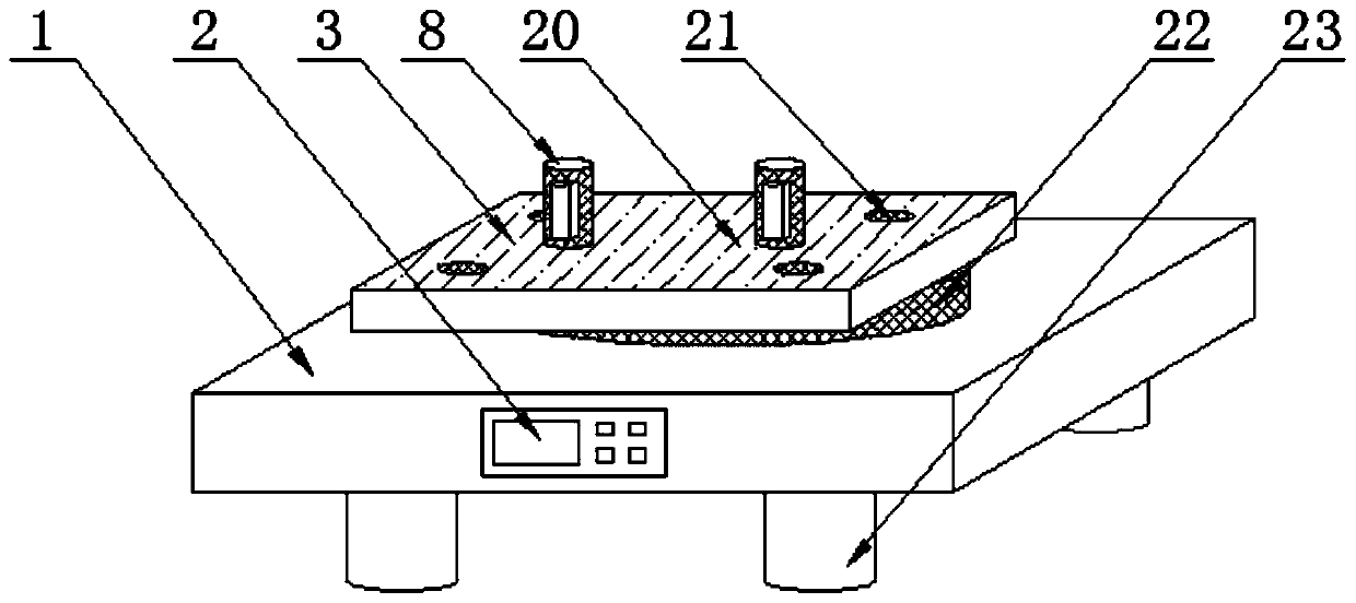
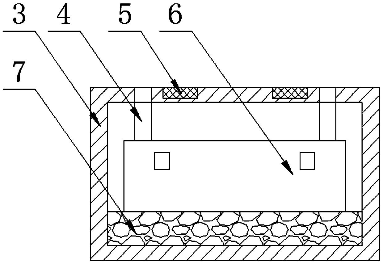
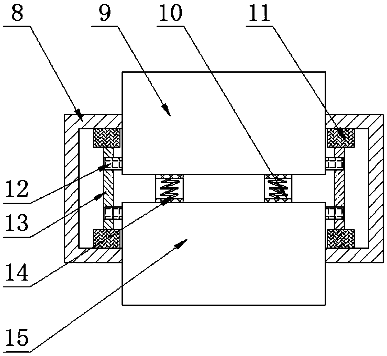
[0017] see Figure 1-4 , the present invention provides a technical solution: a practical fixed fixture for engine connecting rod grinding, including a base 1, a control panel 2, a splint 3, a dust removal pipe 4, a reinforcing rib 5, a dust remover 6, and a backing plate 7 , Installation base 8, first fixed plate 9, coil spring 10, limit block 11, slider 12, slide rail 13, spring seat 14, second fixed plate 15, atomizing nozzle 16, oil delivery pipe 17, oil s...


PUM


Abstract

The invention discloses a high-practicability fixing clamp for polishing a connection rod of an engine. The fixing clamp comprises a base, a control plate, a clamping plate, a dedusting pipe, reinforcement ribs, a dusting machine, a base plate, mounting bases, a first fixing plate, spiral springs, limit blocks, slide blocks, slide rails, spring plates, a second fixing plate, atomization spray nozzles, oil conveying pipes, oil storage tanks, micro oil pumps, a wear-resistance spacer, dedusting ports, a rotation base and supporting columns. The bottom of the base is provided with the supportingcolumns through bolts, one side of the base is provided with the control plate through bolts, and the top of the base is provided with the rotation base through bolts. The top of the rotation base isprovided with the clamping plate through bolts, the top of the clamping plate is provided with the wear-resistance spacer through a connector, and the base plate is installed in the clamping plate through bolts. The fixing clamp is simple in structure and convenient to operate, can stably fix the connection rod of the engine, and has dusting and lubrication functions, and the practicability duringapplication is greatly improved.

Description

technical field [0001] The invention relates to the technical field of engine connecting rod processing machinery, in particular to a highly practical fixing fixture for grinding an engine connecting rod. Background technique [0002] The connecting rod is one of the main parts of the engine, and its processing accuracy is high. Since the connecting rod is an irregular part, it is not easy to clamp during the processing, or the stability of the clamping effect is poor, resulting in low processing efficiency. The clamping method is not only time-consuming and labor-intensive, but also needs to be clamped every time a surface is polished, which also makes the accuracy of the connecting rod not effectively guaranteed, and it is easy to produce waste products. At the same time, when the connecting rod is polished, the grinding produces The dust is scattered everywhere, which is easy to cause certain damage to the operator's body. Therefore, it is necessary to design a practical ...

Claims


Application Information

Patent Timeline
Patent Type & Authority Applications(China)
IPC IPC(8): B24B41/06B24B19/00B24B55/06B24B41/00F16N7/32
CPCB24B19/00B24B41/007B24B41/06B24B55/06F16N7/32
Inventor 何瑞荣
Owner 何瑞荣
Learn More