Electric power steering system and method used for generating steering system

A technology of electric power steering and steering system, which is applied in power steering mechanism, electric steering mechanism, steering mechanism, etc., and can solve problems such as annoying noise, worm shaft and worm gear disengagement, etc.

Active Publication Date: 2020-04-03
TRW AUTOMOTIVE GMBH
View PDF5 Cites 5 Cited by
  • Summary
  • Abstract
  • Description
  • Claims
  • Application Information

AI Technical Summary

Problems solved by technology

These pivotal movements can in turn cause annoying noises, and / or at least at certain disturbance frequencies cause the worm shaft and worm gear to become disengaged

Method used


Image

  • Electric power steering system and method used for generating steering system
  • Electric power steering system and method used for generating steering system
  • Electric power steering system and method used for generating steering system

Examples


Embodiment Construction

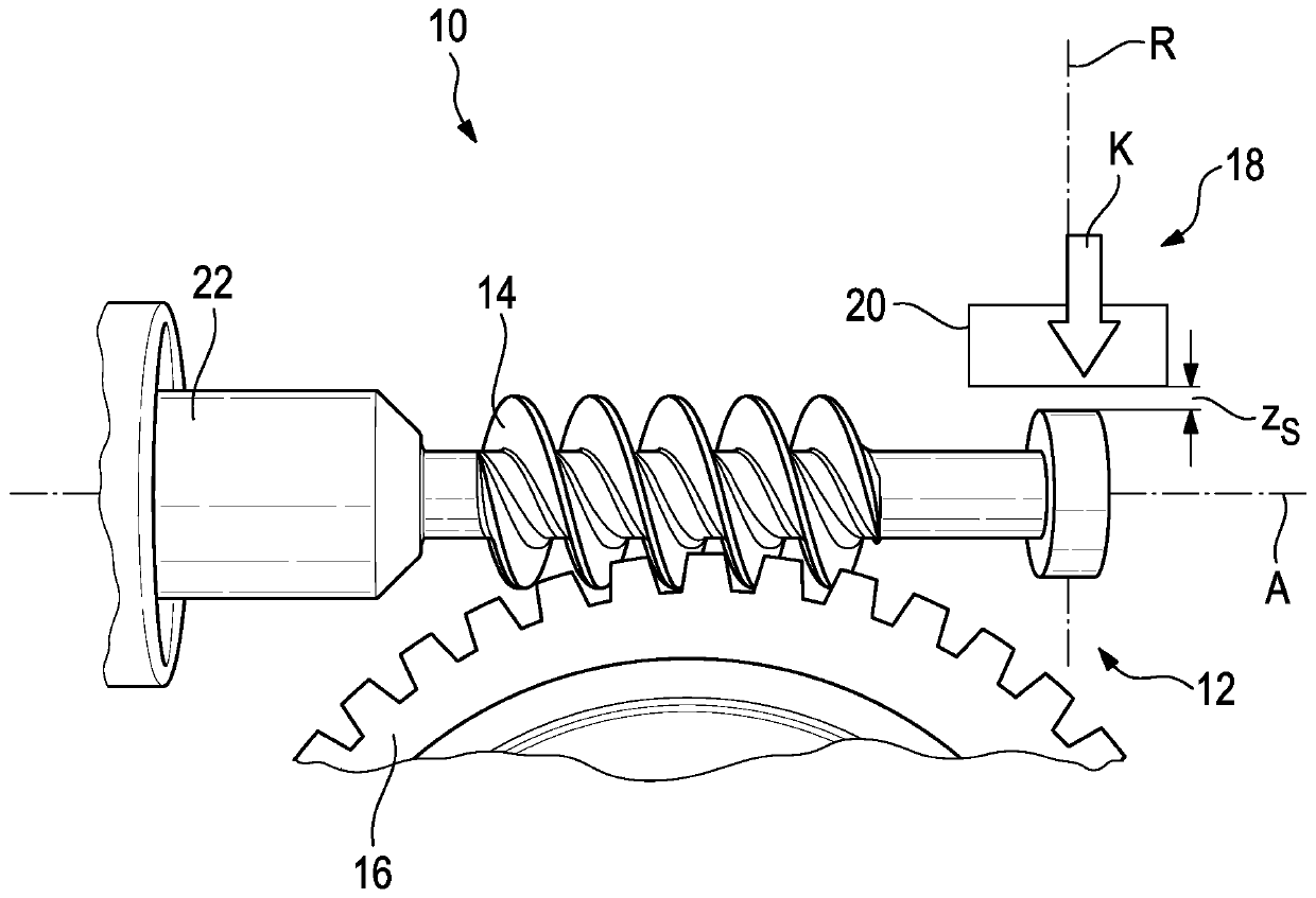
[0034] figure 1 A first variant of the electric power steering system 10 is schematically shown.

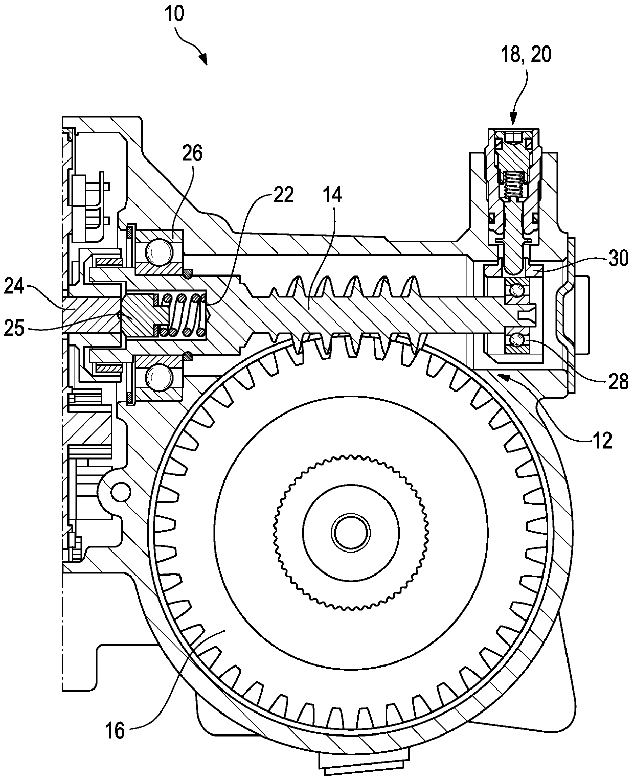
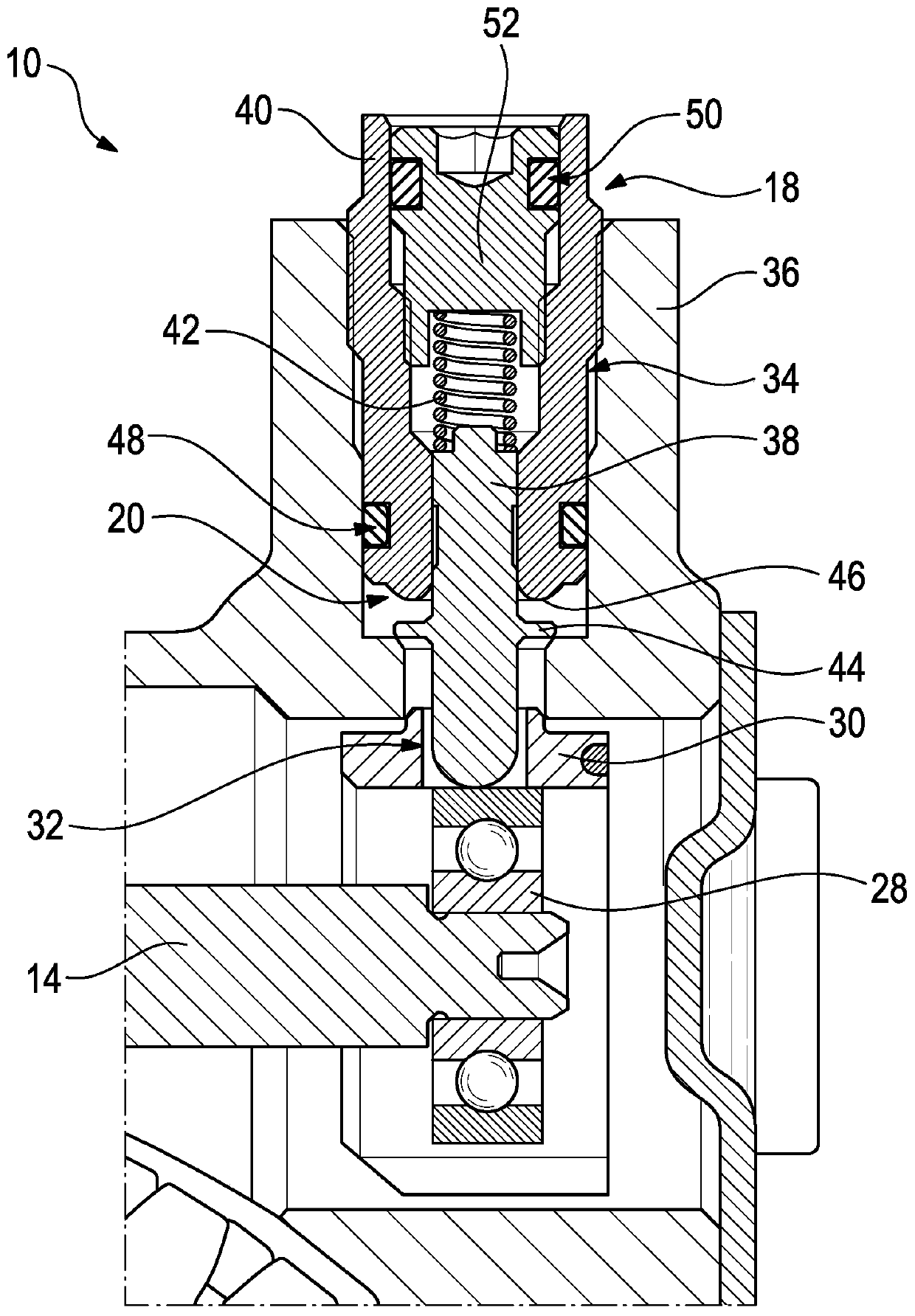
[0035] The steering system 10 includes a worm gear mechanism 12 with a worm shaft 14 and a worm wheel 16 , and also includes a pretensioning device 18 with a limiting device 20 .

[0036] The worm shaft 14 comprises an end 22 (not shown) associated with the electric motor, wherein the electric motor is force-transmittingly connected to the worm shaft 14 and thus also to the worm wheel 16 . The electric motor includes in particular an auxiliary motor of the steering system 10 .

[0037] The worm gear 16 is force-transmittingly coupled to a steering column or rack of the steering system 10 . Thus, this includes an electric power steering system 10 with a steering column drive or a rack and pinion drive.

[0038] exist figure 1 In , the basic operation of the steering system 10 has been indicated, more particularly in relation to the pretensioner 18 and the limiter 20 .

[0039] ...


PUM


Abstract

An electric power steering system with a worm gear includes a worm shaft and a worm wheel, wherein an electric motor is associated with the worm shaft, which is connected to the worm shaft in a force-transmitting manner. A bearing element, arranged on the worm shaft at the end of the worm shaft facing away from the electric motor, is received in a guide bush, wherein the guide bush has, on its circumferential side, a passage opening. It is provided a pre-tensioning device comprising a spring-loaded actuator element extending through the passage opening of the guide bush and acting on the wormshaft in the direction of the worm wheel with a defined pre-tensioning force (K), wherein the pre-tensioning device comprises a limiting device which is adapted to limit a pivoting movement that displaces the worm wheel away from the worm shaft. Furthermore, it is proposed a method for the production of steering systems and a test system for performing the method.

Description

technical field [0001] The invention relates to an electric power steering system, a method for producing a steering system, and a test system for carrying out the method. Background technique [0002] It is known from the prior art that electric power steering systems comprise a worm gear mechanism via which an auxiliary motor of the steering system is connected in a force-transmitting manner to a steering column or to a rack of the steering system. Correspondingly, this includes power steering including a steering column drive or a rack and pinion drive. [0003] Typically, the worm shaft of the worm gear mechanism is pivotally mounted to the associated end of the electric motor, wherein the pivotal movement takes place substantially in the plane defined by the worm wheel of the worm gear mechanism. A pretensioning device can act on the free end of the worm shaft, which pretensioning device has a pretensioning force in the direction of the worm wheel, so that the worm sha...

Claims


Application Information

Patent Timeline
Patent Type & Authority Applications(China)
IPC IPC(8): B62D3/10B62D5/04F16H55/24
CPCB62D3/10B62D5/0454F16H55/24B62D5/0409F16H57/021F16H2057/0213F16H2057/0222F16H2057/127B62D5/0496B62D3/12F16H1/16
Inventor T·米勒S·基施斯泰因
Owner TRW AUTOMOTIVE GMBH
Why Eureka
Try Eureka