Sponge city seepage structure and sponge city water circulation system

A sponge city and water circulation technology, applied in waterway systems, sewer systems, drainage structures, etc., can solve problems such as pipe blockages, and achieve the effects of maintaining water volume, improving utilization, and increasing plant coverage.

Active Publication Date: 2021-01-12
南京金海设计工程有限公司
View PDF1 Cites 1 Cited by
  • Summary
  • Abstract
  • Description
  • Claims
  • Application Information

AI Technical Summary

Problems solved by technology

[0004] However, in the above seepage and drainage structure, since the overflow pipe is not equipped with a corresponding filter device, if there are debris (such as fallen leaves, waste plastics, mud, etc.) on the surface of the seepage, the debris will easily fall into the overflow pipe along with the water flow. , which will cause the pipes in the seepage structure to be blocked after long-term accumulation

Method used


Image

  • Sponge city seepage structure and sponge city water circulation system
  • Sponge city seepage structure and sponge city water circulation system
  • Sponge city seepage structure and sponge city water circulation system

Examples


Embodiment 1

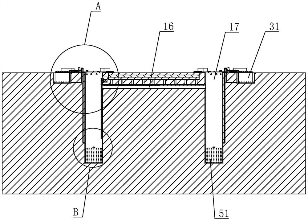
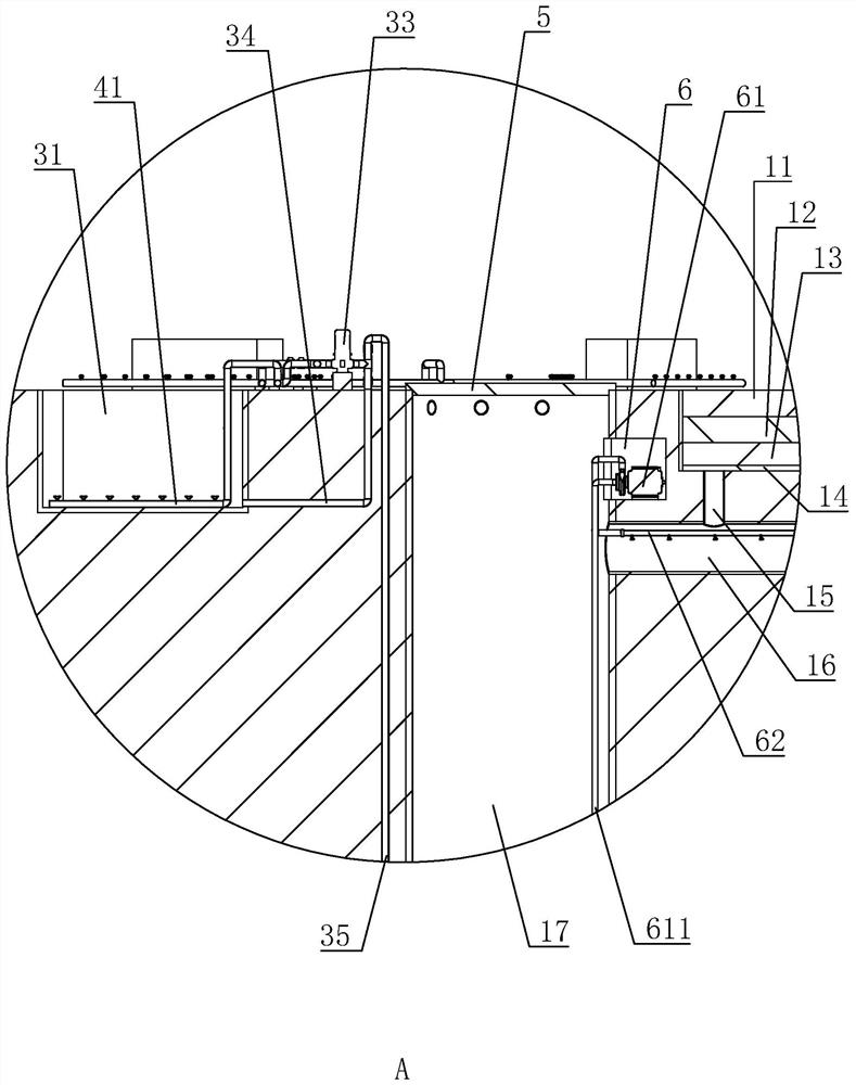
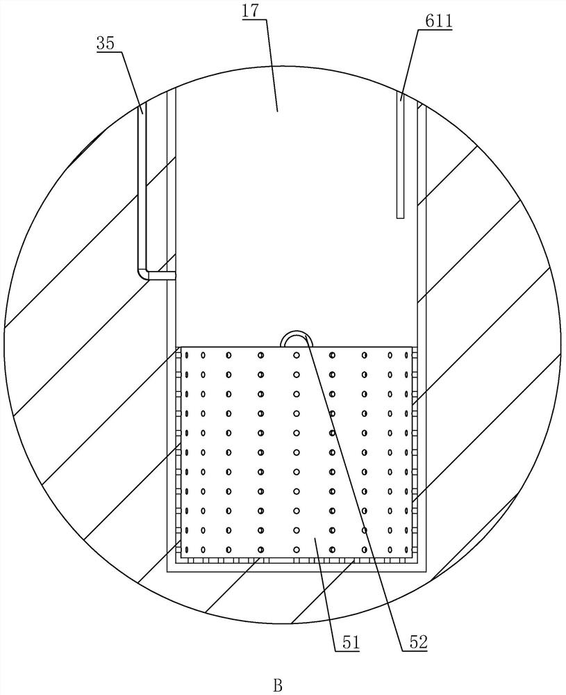
[0042] Embodiment 1: A kind of sponge city seepage drainage structure, such as figure 1 with Figure 4As shown, it includes a trench 1 arranged on the ground, a soil layer 11 laid in the trench 1 and distributed sequentially from top to bottom along the depth direction of the trench 1, a coarse sand layer 12, a fine sand layer 13 and a geotextile 14 , the section of the groove 1 is an inverted trapezoid, and the bottom of the groove 1 is provided with a number of drainage pipes 15 equidistantly distributed along the length direction of the groove 1. The end of each drainage pipe 15 away from the groove 1 is connected by a water pipe 16. Two water collection wells 17, two water collection wells 17 are communicated with the two ends of water delivery pipe 16 respectively, and water collection well 17 wellhead places are provided with well cover 5 (as figure 2 ), to prevent pedestrians from falling into the water collection well 17, and a filter cartridge 51 is also provided in...

Embodiment 2

[0051] Embodiment two: a kind of sponge city water circulation system, such as Figure 9 with Figure 10 As shown, the difference from Embodiment 1 is that the inner wall of the water delivery pipe 16 is provided with a flushing pipe 62 extending along its length direction, and one end of the flushing pipe 62 is closed, and the flushing pipe 62 is provided with several flushing nozzles 621 inclined downward. ; On the inner wall of the water collection well 17, there is a storage tank 6 (such as figure 2 ), the storage tank 6 is provided with a high-pressure pump 61, and the water inlet and outlet ends of the high-pressure pump 61 are respectively connected with a first rubber tube 611 and a second rubber tube 612, and the end surface of the second rubber tube 612 is away from the high-pressure pump 61 A washer 63 is provided, the outer diameter of the washer 63 is the same as that of the flushing pipe 62 and larger than the outer diameter of the second rubber tube 612, the s...


PUM


Abstract

The invention provides a sponge city seepage and drainage structure and a sponge city water circulation system, and relates to the sponge city seepage and drainage structure applied to the technical field of sponge cities. The structure comprises a groove in the ground; a soil layer, a coarse sand layer, a fine sand layer and geotextile which are sequentially distributed in the depth direction ofthe groove from top to bottom are arranged in the groove; a plurality of drainage pipes distributed at intervals in the length direction of the groove are arranged at the bottom of the groove; the end, away from the groove, of each drainage pipe is connected through a water conveying pipe; two water collecting wells are arranged on the ground; and the two water collecting wells communicate with the two ends of the water conveying pipe respectively. The structure has the effect of reducing blockage of pipelines in the seepage and drainage structure.

Description

technical field [0001] The invention relates to the technical field of sponge cities, in particular to a sponge city seepage drainage structure and a sponge city water circulation system. Background technique [0002] Sponge city is a new generation of urban stormwater management concept, which means that the city has good "elasticity" in adapting to environmental changes and responding to natural disasters caused by rainwater. It can also be called "water elastic city". Its main functions When it rains, absorb water, store water, infiltrate water, purify water, and "release" the stored water and make use of it when needed. [0003] The Chinese patent with the notification number CN206591602U discloses a sponge city seepage structure and a sponge city water circulation system, including a sponge city seepage structure, a net stagnation structure and a water use structure connected in sequence, wherein the seepage surface of the sponge city seepage structure runs through A p...

Claims


Application Information

Patent Timeline
Patent Type & Authority Patents(China)
IPC IPC(8): E03F3/02E03F3/04E03F5/10E03F5/14
CPCE03F3/02E03F3/04E03F5/10E03F5/14
Inventor 徐媛张童嘉陈宏业
Owner 南京金海设计工程有限公司
Why Eureka
Try Eureka