
Vacuum drainage electroless mechanical micro-air pressure opening structure and use method thereof

A technology of vacuum drainage and micro-air pressure, which is applied in the direction of mechanical equipment, engine components, valve details, etc., can solve the problems of power consumption, leakage, equipment rust, etc., and achieve the effect of wide promotion and application, small trigger air pressure and simple structure

Active Publication Date: 2020-04-03
厚力德机器(杭州)有限公司
View PDF6 Cites 0 Cited by
  • Summary
  • Abstract
  • Description
  • Claims
  • Application Information

AI Technical Summary

Problems solved by technology

[0002] In current life, valves are the control components that ensure the normal flow of fluids. Conventional valves are mainly driven by liquid buoyancy or electric power. Although the drive does not consume energy, there are often many impurities in the water flow, which can easily cause equipment to rust or get stuck, shorten the service life of the opening structure, and cause high failures.

Method used


Image

  • Vacuum drainage electroless mechanical micro-air pressure opening structure and use method thereof
  • Vacuum drainage electroless mechanical micro-air pressure opening structure and use method thereof
  • Vacuum drainage electroless mechanical micro-air pressure opening structure and use method thereof

Examples


Embodiment Construction

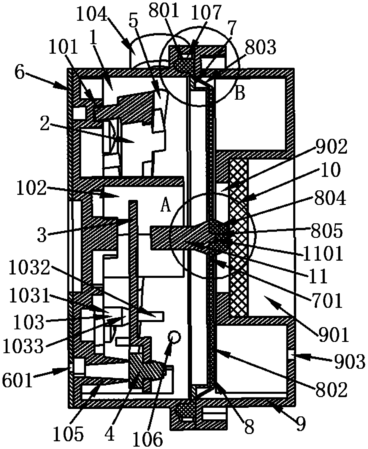
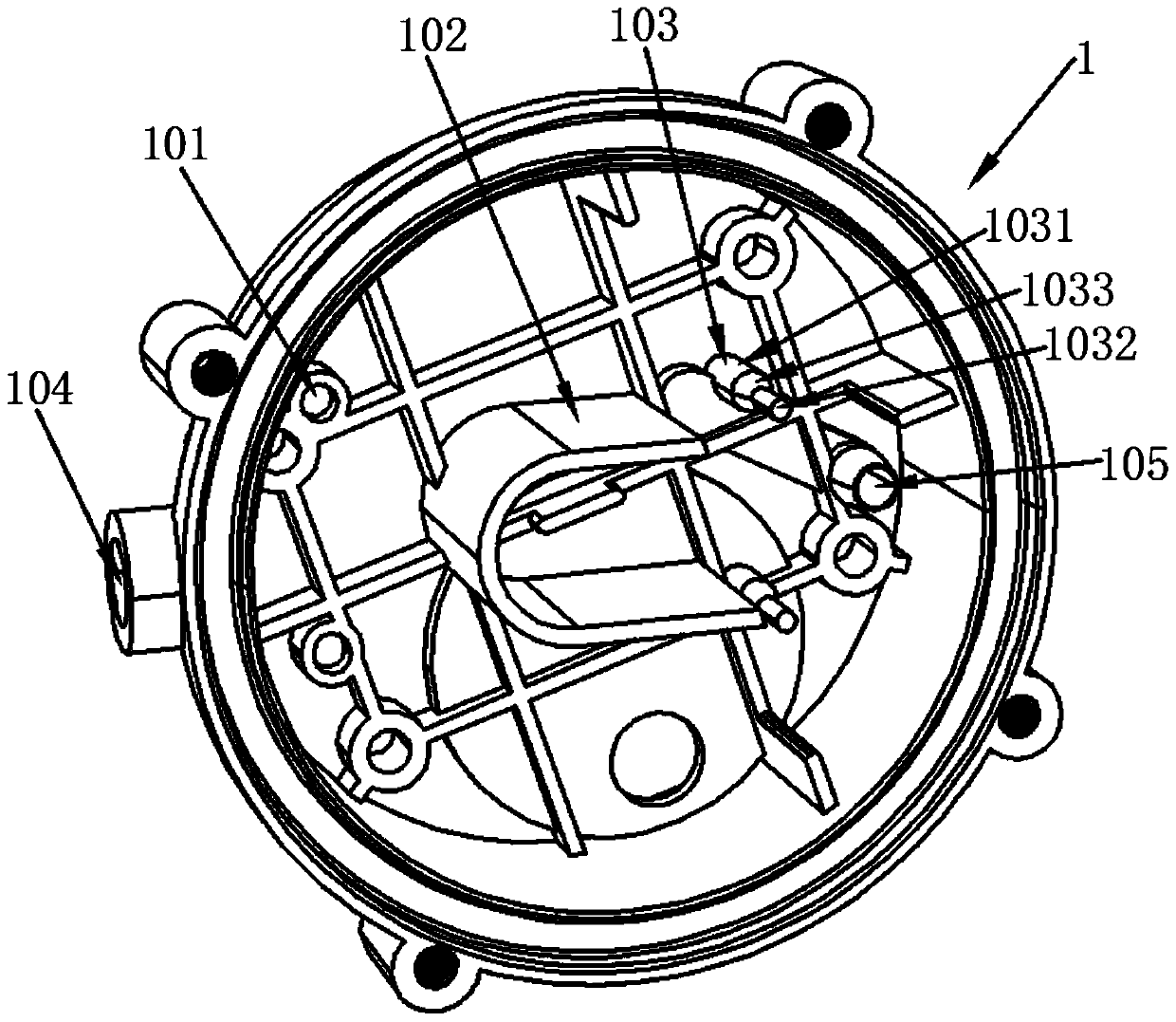
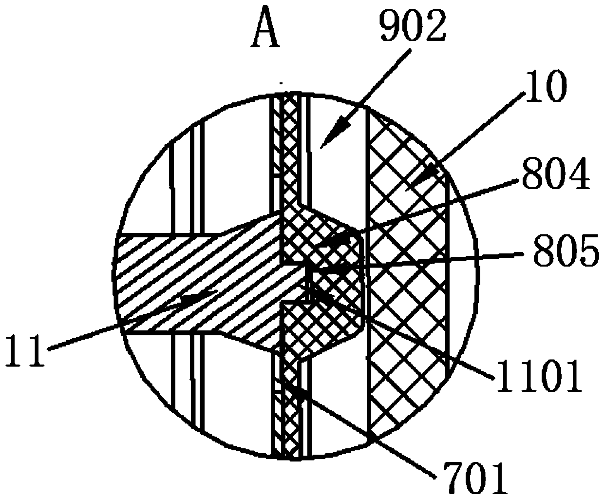
[0032] refer to Figure 1-Figure 9 , a vacuum drainage non-electric mechanical micro-pressure opening structure and its use method of the present invention, comprising a main housing 1, a U-shaped pressing plate 2, a Z-shaped seesaw 3, a rubber block 4, a reset push rod 5, a top cover 6, a support Plate 7, rubber membrane 8, fixed cover 9, rubber blocking plate 10 and working column 11, the main housing 1 is provided with a circular groove 101, a U-shaped baffle 102 and a central pillar 103, the circular groove 101 and the number of middle pillars 103 are two, the circular groove 101 and the middle pillar 103 are respectively located on both sides of the U-shaped baffle plate 102, the main housing 1 is also provided with a tapered tube 105, and the lower part of the tapered tube 105 is a cylinder 1031 is connected with the upper upper cylinder 1032 of the tapered pipe 105 through a conical inclined surface 1033, a small circular hole 104 is provided on the outside of the side ...


PUM

PropertyMeasurementUnit
thicknessaaaaaaaaaa

Abstract

The invention discloses a vacuum drainage electroless mechanical micro-air pressure opening structure and a use method thereof. The vacuum drainage electroless mechanical micro-air pressure opening structure includes a main casing, a U-shaped pressing plate, a Z-shaped wrap plate, a rubber block, a reset push rod, a top cover and a rubber membrane, the main casing is provided with circular grooves, a U-shaped baffle and center pillars, and further provided with a taper pipe, and an air inlet is further formed in the outer side of the main casing; a long tongue board is arranged at one end of amain plate of the Z-shaped wrap plate, a small tongue plate of the Z-shaped wrap plate and the main plate are connected by a connecting plate, a rubber installation hole of the small tongue plate isinternally provided with the rubber block, two holes in the main plate correspondingly sleeve the conical inclined plane, and the long tongue plate is located inside the U-shaped baffle; a support column is arranged in the circular groove, and a groove is formed in the rear side of the middle part of a main body rod of the U-shaped pressing plate; a toggle rod is pressed on wrap rods at both endsof the main plate; and a small round hole is internally and slidably provided with the reset push rod. According to the vacuum drainage electroless mechanical micro-air pressure opening structure, a valve can be opened by micro-air pressure drive, opening force is small, a lever and air work together, and the reliability is high.

Description

【Technical field】 [0001] The invention relates to the technical field of valves, in particular to the technical field of a vacuum drainage non-electric mechanical micro-pressure opening structure and a use method thereof. 【Background technique】 [0002] In current life, valves are the control components that ensure the normal flow of fluids. Conventional valves are mainly driven by liquid buoyancy or electric power. Although the drive does not consume energy, there are often many impurities in the water flow, which can easily cause equipment to rust or get stuck, shorten the service life of the opening structure, and cause high failures. For this reason, it is necessary to improve and design the valve opening structure for the existing problems of the valve opening structure. 【Content of invention】 [0003] The purpose of the present invention is to solve the problems in the prior art, and propose a vacuum drainage non-electric mechanical micro-pressure opening structure ...

Claims


Application Information

Patent Timeline
Patent Type & Authority Applications(China)
IPC IPC(8): F16K31/12F16K31/44
CPCF16K31/12F16K31/44
Inventor 孙富强连加俤
Owner 厚力德机器(杭州)有限公司
Learn More