
Amphibious high-current switch

A high-current switch, amphibious technology, applied in the direction of electric switch, magnetic/electric field switch, circuit, etc., can solve the problems of unbearable high current, low reliability, inconvenient operation, etc. Long, powerful effect

Inactive Publication Date: 2020-04-03
750 TEST SITE OF CHINA SHIPBUILDING IND CORP
View PDF15 Cites 1 Cited by
  • Summary
  • Abstract
  • Description
  • Claims
  • Application Information

AI Technical Summary

Problems solved by technology

The sealing ring is used as a waterproof dynamic seal, which is easily affected by changes in water depth, aging and wear of the sealing ring, and has low reliability; sealing with a sealing cover is inconvenient to operate, and it cannot be directly powered on and off underwater, so it is not suitable for carrying people equipment
[0003] The switches used in the air in the prior art are not waterproofed, and cannot be directly applied underwater; while the magnetic induction underwater switches in the prior art have a unique shape and structure, or require an external magnet, and have low reliability in deep water conditions. In the air, it is inconvenient to operate and cannot withstand large currents
[0004] After checking, there is an "underwater electrical switch (CN207319972U)" that can withstand high voltage, but it uses an "O"-shaped sealing ring for dynamic sealing, and the sealing ring needs to be replaced frequently, and the movable part of the spring is not designed for pressure balance. When used in shallow water, the switch will be incorrectly connected due to the influence of water pressure in deep water; The lateral attractive force between the two magnets conducts force transmission, which is not as strong as the force of positive relative movement, so it is not the best design. In this design, there will be current on magnet B when the switch is turned on, and it will change after multiple uses. The magnetic field distribution of magnet B, magnet B degaussing is faster, not suitable for long-term use; "a separate underwater switch (CN206628417U)" uses a magnet to control the on-off of the reed switch, and then uses the reed switch to control the on-off of the relay. Thereby relays are used to control the on-off of the power supply, but the reed switch is susceptible to false conduction due to the influence of the surrounding magnetic field. When the switch is used, it must be ensured that there is no strong magnetic field around it; "An underwater self-locking induction switch (CN203707018U) Both "a separate underwater switch (CN206628417U)" use magnetic switches, which have similar shortcomings; "a waterproof switch for underwater drones and underwater drones (CN205810631U)" also uses "O" It is not suitable for deep water; "An elastic protective film key switch structure for underwater use (CN108257807A)" is filled with hydraulic oil and has a pressure balance mechanism, which can be used in deep water. It belongs to the touch button, which cannot maintain the state, and cannot directly pass a large current; "a mode selection switch for underwater equipment (CN204557134U)" cannot pass a large current; Switch (CN107578951A)" avoids the problem of dynamic sealing. Its design can meet the use under deep water conditions and has the ability to flow large currents. However, in its embodiment two, the copper sheet and the magnet are directly bonded and connected. After the magnet flows through the current It is easy to demagnetize, and the number of effective uses is low. In Example 1, when the steel sheet is close to the magnet, the magnet can pick up the steel sheet. However, since the steel sheet does not have a strong directional magnetic field, it cannot be effectively used when the external bar magnet rotates. Ensure that the steel sheet also rotates, the reliability of this switch is low in actual use

Method used


Image

  • Amphibious high-current switch
  • Amphibious high-current switch
  • Amphibious high-current switch

Examples


Embodiment Construction

[0032] The specific implementation manners of the present invention will be described in more detail below in conjunction with the accompanying drawings and specific embodiments.

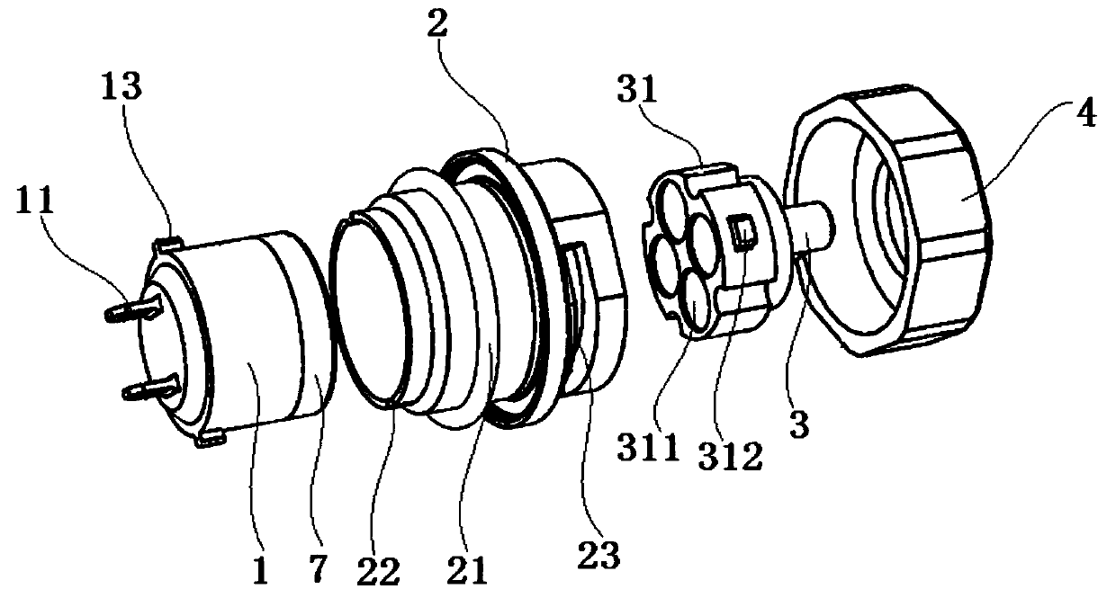
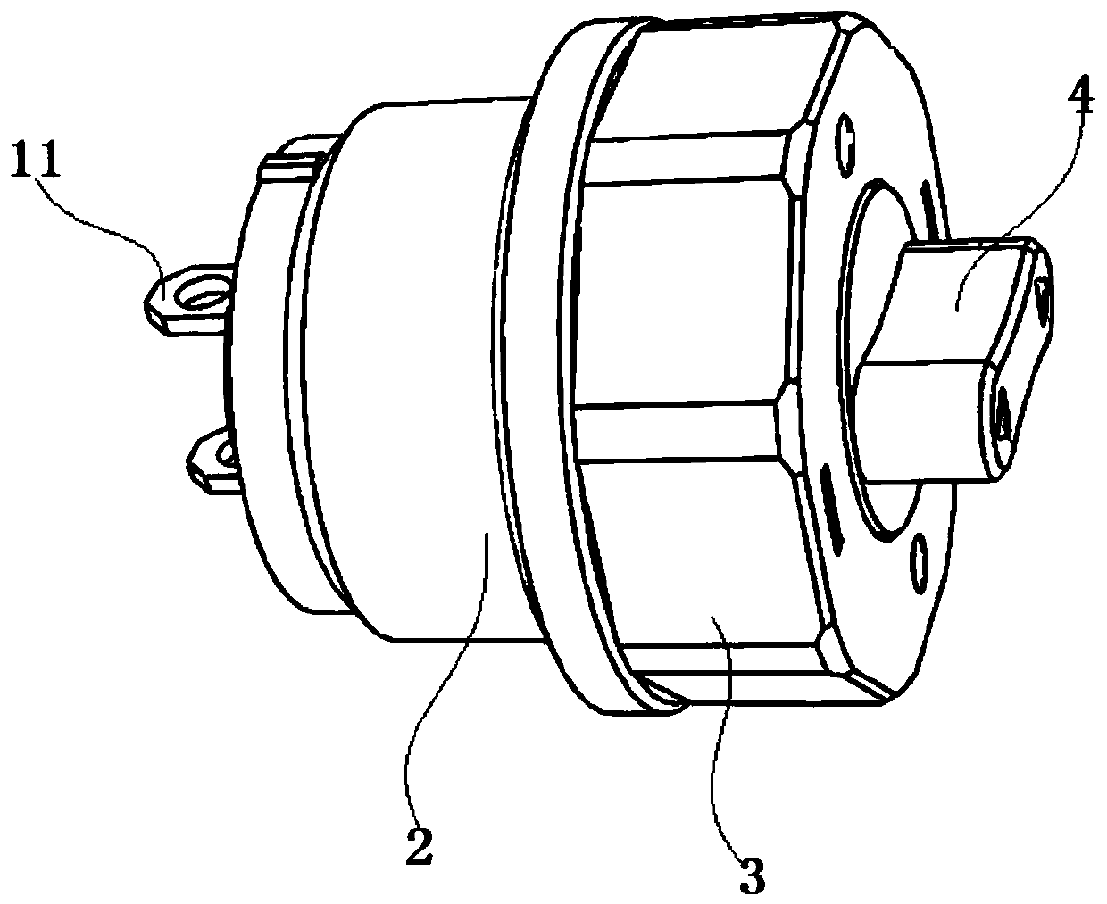
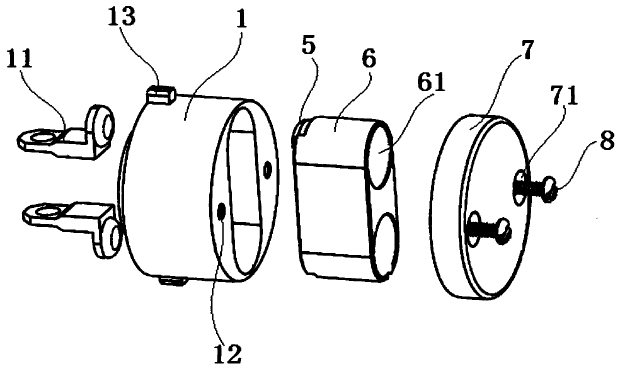
[0033] As attached to the manual Figure 1-6 As shown, the amphibious high-current switch includes a contact base 1, a switch housing 2, a switch knob 3, and a switch cap 4. The bottom of the contact base 1 is provided with a separate switch contact 11, and the interior of the contact base 1 is provided with There are one-piece switch contact 5, magnet seat 6, two permanent magnets 61 and contact seat upper cover 7; the contact base 1 is installed on the bottom of the switch housing 2, and the switch housing 2 is also provided with a sealing ring 21, the switch The knob 3 is fixed inside the upper end of the switch housing 2 through the switch cap 4, and the bottom of the switch knob 3 is also provided with a magnet base 31 and four permanent magnets 311, wherein the contact base 1, the contact base...


PUM


Abstract

The invention discloses an amphibious high-current switch, which comprises a contact base (1), a switch shell (2), a switch knob (3) and a switch turncap (4), and is characterized in that: a separatedswitch contact (11) is arranged at the bottom of the contact base (1), and an integrated switch contact (5), a magnet seat (6), two permanent magnets (61) and a contact seat upper cover (7) are arranged in the contact base (1); the contact base (1) is arranged at the bottom of the switch shell (2); the switch shell (2) is also provided with a sealing ring (21); and the switch knob (3) is fixed inside the upper end of the switch shell (2) through the switch turncap (4), and the bottom of the switch knob (3) is also provided with a magnet seat (31) and four permanent magnets (311). The structure is statically sealed only by an O-shaped ring, and pressure compensation is designed, so that the closing and opening of the switch are not influenced by water depth, and the use is safe and reliable; the permanent magnet in the switch is not easy to demagnetize, and the service life is long; and moreover, the switch is not easily interfered by an external magnetic field, has a state maintainingcapability, and can directly pass through a large current.

Description

technical field [0001] The invention belongs to the technical field of underwater high-current switches, and in particular relates to amphibious high-current switches. Background technique [0002] Existing switches installed in underwater equipment such as underwater vehicles, underwater entertainment equipment, and seabed exploration equipment mainly use "O"-shaped sealing rings for dynamic sealing, or seal the switch control part with a separate sealing cover. . The sealing ring is used as a waterproof dynamic seal, which is easily affected by changes in water depth, aging and wear of the sealing ring, and has low reliability; sealing with a sealing cover is inconvenient to operate, and it cannot be directly powered on and off underwater, so it is not suitable for carrying people equipment. [0003] The switches used in the air in the prior art are not waterproofed, and cannot be directly applied underwater; while the magnetic induction underwater switches in the prior ...

Claims


Application Information

Patent Timeline
Patent Type & Authority Applications(China)
IPC IPC(8): H01H19/06H01H19/08H01H19/14H01H19/20H01H36/00
CPCH01H19/065H01H19/08H01H19/14H01H19/20H01H36/00
Inventor 罗金旺张希刘显龙李晓峰马振东陈诚
Owner 750 TEST SITE OF CHINA SHIPBUILDING IND CORP
Learn More