Movable spring structure capable of preventing breakage and mis-connection and electromagnetic relay

An electromagnetic relay, misconnection technology, applied in electromagnetic relays, electromagnetic relay details, relays, etc., can solve the problems of misconnection of the static spring part, affecting the safety of the relay, tilting and falling, etc., to improve safety, Easy assembly, avoid deformation or breakage effect

Pending Publication Date: 2020-04-03
ZHANGZHOU HONGFA ELECTROACOUSTIC CO LTD
View PDF0 Cites 0 Cited by
  • Summary
  • Abstract
  • Description
  • Claims
  • Application Information

AI Technical Summary

Problems solved by technology

However, this kind of relay also has the following disadvantages: once the moving spring part breaks, the moving spring part will fall into the base at an angle, and there is a possibility of mistaken connection with the static spring part, thus affecting the safety of the relay

Method used


Image

  • Movable spring structure capable of preventing breakage and mis-connection and electromagnetic relay
  • Movable spring structure capable of preventing breakage and mis-connection and electromagnetic relay
  • Movable spring structure capable of preventing breakage and mis-connection and electromagnetic relay

Examples


Embodiment 1

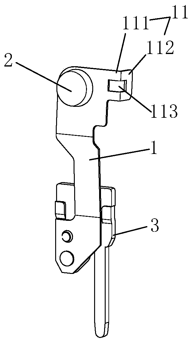
[0031] Example 1, please refer to figure 1 , figure 2 As shown, a kind of moving spring structure of the present invention to prevent breakage and mistaken connection is used for relays, including a moving reed 1, and the head of the moving reed 1 is provided with a moving contact 2; the head of the moving reed 1 is provided with a Hang on the L-shaped hooking portion 11 on the push card of the relay, and the L-shaped hooking portion 11 includes one side along the width direction of the moving reed 1 (the side can be any direction in the width direction of the moving reed 1). The first extension part 111 extends from the first extension part 111 to the side where one side of the moving reed 1 is located.

[0032] In this embodiment, the number of the L-shaped hooking portion 11 is one, and the second extension portion 112 of the L-shaped hooking portion 11 is located on opposite sides of the moving reed 1 to the movable contact 2 . The L-shaped hooking portion 11 defines a...

Embodiment 2

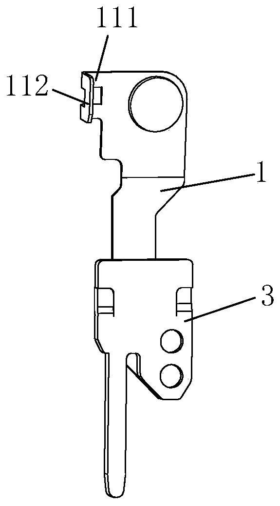
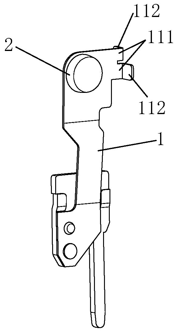
[0036] See image 3 , Figure 4As shown, the moving spring structure of the present invention to prevent breakage and mistaken connection differs from the first embodiment above in that: the number of the L-shaped hooking parts 11 is two, and the two L-shaped hooking parts 11 are located on the same side of the moving reed 1 and distributed up and down, and the second extensions 112 of the two L-shaped hooking parts 11 are located on opposite sides of the moving reed 1 .

[0037] See Figure 5-Figure 10 As shown, an electromagnetic relay of the present invention includes a base 10, and a magnetic circuit part 20, a moving spring part, and a static spring part arranged on the base 10. The magnetic circuit part 20 is connected and matched with the moving spring part through a push card 30. , The moving spring part corresponds to the static spring part. The moving spring part adopts the moving spring structure described in the above-mentioned embodiment 1 or embodiment 2 to pr...


PUM


Abstract

The invention discloses a movable spring structure capable of preventing breakage and mis-connection and an electromagnetic relay, the movable spring structure is used for the relay and comprises a movable spring sheet, and the head of the movable spring sheet is provided with a movable contact; the head of the movable contact spring is provided with an L-shaped hanging part used for being hung onthe pushing card of the relay, and the L-shaped hanging part comprises a first extending part extending towards one side in the width direction of the movable contact spring and a second extending part extending from the tail end of the first extending part to the side where one side of the movable contact spring is located in a bent mode. When the movable spring structure is applied to the relay, the movable spring structure has a forced guiding effect, and can be firmly hung on the pushing card of the relay by utilizing the L-shaped hanging part, so that even if the movable spring is broken, the movable spring does not fall into the base of the relay, the movable spring is prevented from being mistakenly connected with the static spring part of the relay, and the safety of the relay isimproved.

Description

technical field [0001] The invention relates to the technical field of relays, in particular to a movable spring structure and an electromagnetic relay for preventing breakage and false connection. Background technique [0002] Electromagnetic relay is an electronic control device. Its basic working principle is to convert electrical energy into magnetic energy and then into mechanical energy, and use mechanical energy to connect and break the controlled circuit to realize the function of "relay". An electromagnetic relay in the prior art has a horizontal magnetic circuit part and is connected and matched with the moving spring part through a push card. Specifically, the push card is provided with a limit groove, and the movable spring part is stuck in the limit groove. When the push card moves forward, the rear groove wall of the limit groove of the push card pushes the movable spring part to move forward, and when the push card moves backward At the same time, the front g...

Claims


Application Information

Patent Timeline
Patent Type & Authority Applications(China)
IPC IPC(8): H01H50/56H01H50/58
CPCH01H50/56H01H50/58
Inventor 赖立芹林正极刘金枪
Owner ZHANGZHOU HONGFA ELECTROACOUSTIC CO LTD
Why Eureka
Try Eureka