Wire stabilizing and stripping machine

A wire stripping machine and wire stabilizing technology, which is applied in the direction of cable installation devices, electrical components, equipment for dismantling/armoring cables, etc., can solve the problems of cable deviation from the blade, difficulty in cutting wires, and failure of the cable to align with the blade, etc., to achieve The effect of promoting deviation and preventing deviation

Pending Publication Date: 2020-04-03
TAIZHOU SENDUO ENVIRONMENTAL PROTECTION EQUIP TECH CO LTD
View PDF1 Cites 5 Cited by
  • Summary
  • Abstract
  • Description
  • Claims
  • Application Information

AI Technical Summary

Problems solved by technology

[0004] During the use of the above-mentioned multifunctional wire stripping machine, it was found that during the cutting process of the cable insulation, when the blade comes into contact with the cable, the blade will exert force on the insulation, and at the same time, the cross section of the cable is usually round. Therefore, when the shear force is applied to the surface of the cable, it will inevitably deflect, which will cause the cable to deviate from the blade. In this process, the larger the diameter of the cable, the greater its rigidity, and the cable will be affected by the shear force. And when the deviation occurs, the greater the force applied to the hand, the operator may not be able to stabilize the direction of the cable, causing the cable to be unable to align with the blade, resulting in difficulty in thread cutting

Method used


Image

  • Wire stabilizing and stripping machine
  • Wire stabilizing and stripping machine
  • Wire stabilizing and stripping machine

Examples


Embodiment Construction

[0033] The present invention will be described in further detail below in conjunction with the accompanying drawings.

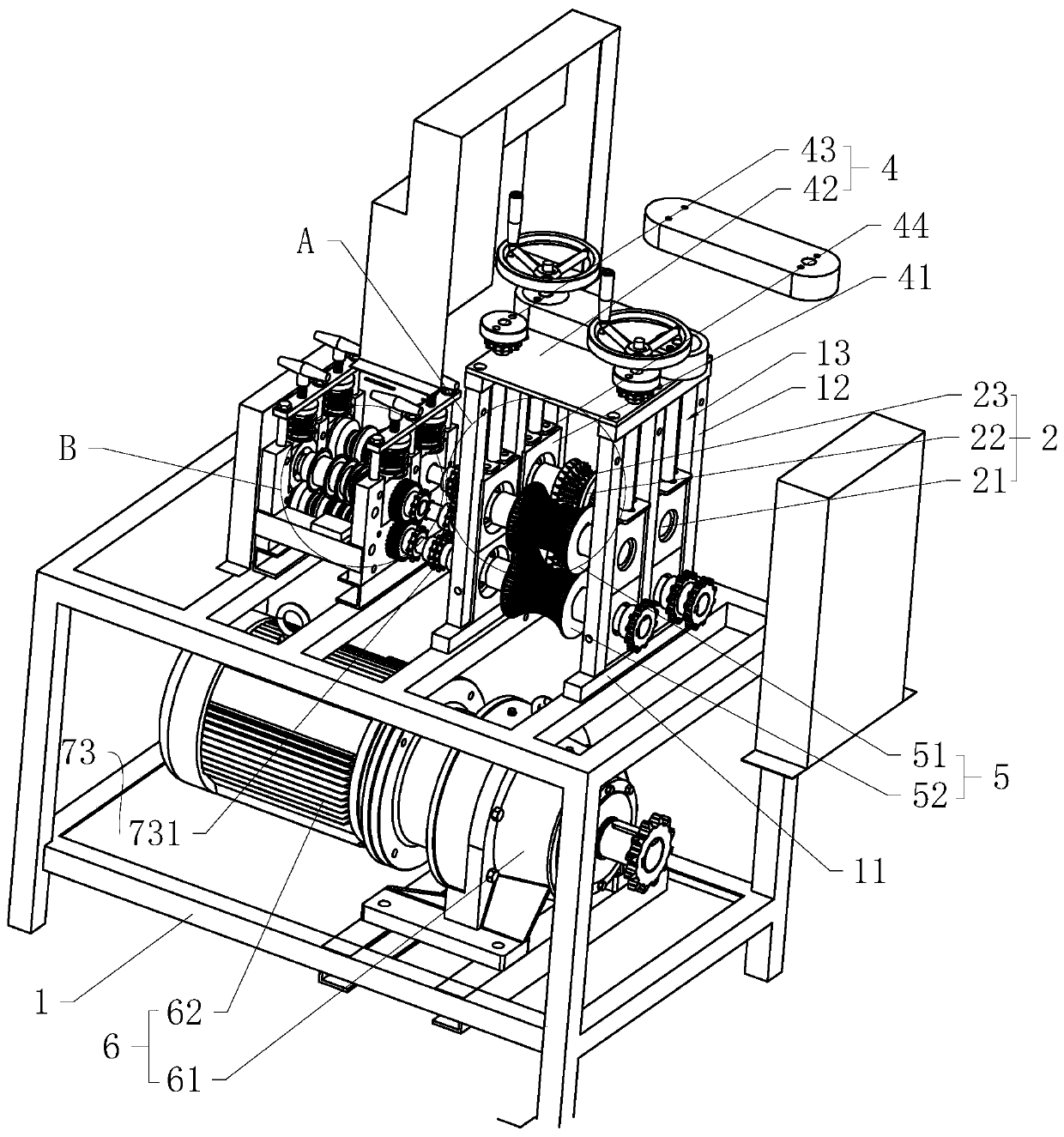
[0034] like figure 1 As shown, a wire-stabilizing stripping machine includes a bracket 1, an upper nip roller 2, a lower nip roller 3, a wire-stabilizing mechanism 5, and a driving mechanism 6. The bracket 1 is used as a supporting body on which two installations opposite to each other are fixed. Each mounting frame 11 has three uprights 12, and an installation space 13 is formed between two adjacent uprights 12.

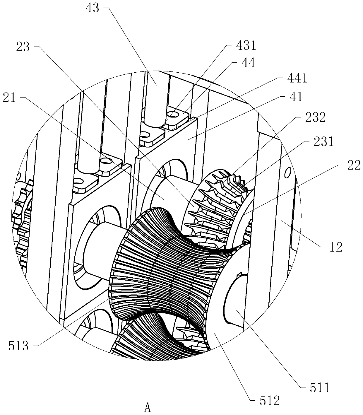
[0035] like figure 2 As shown, the upper nip roller 2 and the lower nip roller 3 have the same structure, both of which include a rotating shaft 21, a blade 22, and an alignment wheel 23, and the rotating shaft 21 is in the shape of a round stick; the blade 22 is sleeved on the rotating shaft 21, And it is located at the center of the rotating shaft 21, and the section of the through hole in the center of the blade 22 for cooperating with the ro...


PUM


Abstract

The invention discloses a wire stabilizing and stripping machine, relates to a wire stripping device, and aims to solve the problem of deviation during cable cutting. The machine comprises a support,an upper clamping roller and a lower clamping roller which are rotationally installed on the support, a driving mechanism arranged on the support, and a wire stabilizing mechanism; the wire stabilizing mechanism comprises a lower wire roller rotationally installed on the support, an upper wire roller arranged on the support in a lifting mode, and a lifting assembly arranged on the support and usedfor adjusting the upper wire roller to ascend and descend;and each of the upper wire roller and the lower wire roller comprises a wire roller shaft and a wire stabilizing sleeve column mounted on thewire roller shaft, the circumferential side wall of each wire stabilizing sleeve column is sunken inwards to form a waist drum-shaped structure, and an arc-shaped wire clamping opening is formed between the upper wire roller and the lower wire roller. The wire stabilizing and stripping machine has the following advantages and effects that the upper wire roller and the lower wire roller can clampa cable, deviation of the cable in the cutting process is limited, the cable can be aligned with the blade all the time, and therefore, the cable can be cut stably and accurately.

Description

technical field [0001] The invention relates to wire stripping equipment, in particular to a stable wire stripping machine. Background technique [0002] Social civilization has gone through the age of steam, the age of internal combustion engines, and the age of electricity, and now it has entered the age of information. As time goes by, technology is always improving. In the context of the information age, all information can be transmitted quickly through electrical signals, and the transmission of electrical signals requires the use of specific media—cables as carriers. After these cables are used up, their materials can be transmitted. For recycling, the old metal in the cable is generally re-melted and cast into other products as needed. [0003] At present, the invention patent with the authorized notification number CN204407105U discloses a multifunctional wire stripping machine, which includes a support arranged on the frame, an upper rotating shaft and a lower rot...

Claims


Application Information

Patent Timeline
Patent Type & Authority Applications(China)
IPC IPC(8): H02G1/12
CPCH02G1/1248H02G1/1256
Inventor 缪继球
Owner TAIZHOU SENDUO ENVIRONMENTAL PROTECTION EQUIP TECH CO LTD
Why Eureka
Try Eureka