Coil element structure of motor flat enameled wire winding

A technology of enameled wire winding and coil components, applied in the shape/style/structure of winding conductors, electrical components, electromechanical devices, etc., which can solve the problems of increased probability of damage to insulating coatings and insulation risks

Pending Publication Date: 2020-04-03
ZHEJIANG LOONGSON ELECTRIC DRIVE TECH CO LTD
View PDF0 Cites 0 Cited by
  • Summary
  • Abstract
  • Description
  • Claims
  • Application Information

AI Technical Summary

Problems solved by technology

[0005] In the above structure, while obtaining higher power density and higher conductor filling rate, the coil element 7, coil element 8, and coil element 9 produce spatial interference 13 with the coil element 10, coil element 11, and coil element 12, resulting in insulation The probability of coating damage increases, and there is a risk of insulation

Method used


Image

  • Coil element structure of motor flat enameled wire winding
  • Coil element structure of motor flat enameled wire winding
  • Coil element structure of motor flat enameled wire winding

Examples


Embodiment

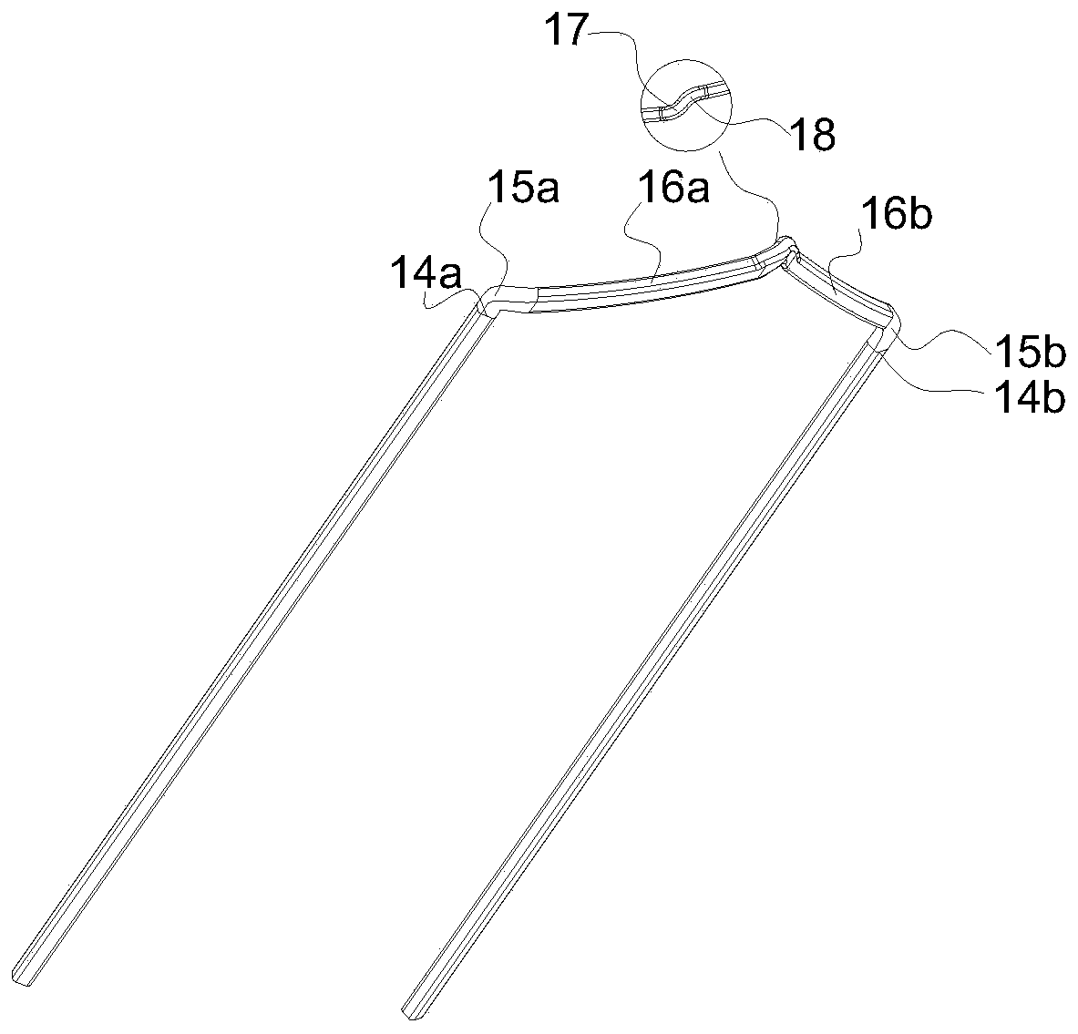
[0021] Such as image 3 and Figure 4 As shown, the coil element structure of the motor flat enameled wire winding of the present invention is composed of ends, bending angles, meander lines, inner bending points and outer bending points connected to each other; 14a and transition 14b are coil element ends, 15a and 15b are bending angles, 16a and 16b are meandering lines, 17 is an inner bending point, and 18 is an outer bending point.

[0022] In this embodiment, a flattened section with a certain length is provided between the end and the bending angle to produce a certain plastic deformation, and the flattened section is flattened on both sides toward the center and toward the center. A flattened section that produces 10%-30% plastic deformation.

[0023] In this embodiment, the crushed length of the crushed section is 10-80 mm.

[0024] Wherein, the section 19 is the section before the deformation of the flattened section, and the section 20 is the section after the defo...


PUM


Abstract

The invention aims at disclosing a coil element structure of a motor flat enameled wire winding. The coil element structure is formed by communicating an end part, a bending angle, a zigzag line, an inner bending point and an outer bending point, and a flattening section which generates certain plastic deformation and has a certain length is arranged between the end part and the bending angle; compared with the prior art, a flattening measure is adopted from the end part of the coil element structure to the zigzag line of the coil element structure, so that the interference problem when the inner layer and the outer layer of the winding are directly stacked is reduced or eliminated on the premise of ensuring the assembly reliability of the motor, and the purpose of the invention is achieved.

Description

technical field [0001] The invention relates to a coil element structure of a motor winding, in particular to a coil element structure of a motor flat enameled wire winding. Background technique [0002] The motor armature winding is usually composed of round enameled wire or flat enameled wire. Compared with round enameled wire, flat enameled wire has higher power density and higher conductor filling rate. With the increase of power density and speed, the AC loss of the motor is more serious (AC resistance increases Big). [0003] In order to solve the above problems, under normal circumstances, in order to pursue higher power density and higher conductor filling rate, the innermost and outermost windings of the winding coil are directly stacked and arranged, and the middle layers are arranged in a staggered and crossed manner. [0004] Such as figure 1 and figure 2 As shown, the coil element 1a and the coil element 1b are directly arranged together in the outermost lay...

Claims


Application Information

Patent Timeline
IPC IPC(8): H02K3/04
CPCH02K3/04H02K2213/03
Inventor 王丽
Owner ZHEJIANG LOONGSON ELECTRIC DRIVE TECH CO LTD
Why Eureka
Try Eureka