
A kind of multi-node audio and video information synchronization sharing display method

An information synchronization, audio and video technology, applied in the field of communication, can solve the problems of few applications, achieve the effect of ensuring reliable communication, realizing full utilization of channel resources, and avoiding channel competition and conflict

Active Publication Date: 2021-11-05
BEIJING HANGXING MACHINERY MFG CO LTD
View PDF5 Cites 0 Cited by
  • Summary
  • Abstract
  • Description
  • Claims
  • Application Information

AI Technical Summary

Problems solved by technology

Domestic time-triggered Ethernet has a certain application foundation in the field of industrial control, but there are few applications in audio and video multi-view scene display such as multi-angle synchronous observation, military cooperative combat situation awareness, and large-scene high-synchronization 3D imaging.

Method used


Image

  • A kind of multi-node audio and video information synchronization sharing display method
  • A kind of multi-node audio and video information synchronization sharing display method
  • A kind of multi-node audio and video information synchronization sharing display method

Examples


Embodiment 1

[0021] In this embodiment, the multi-node audio and video information synchronous sharing display method includes the following steps:

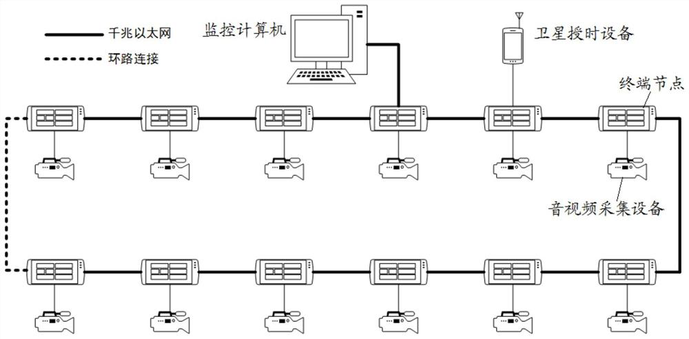
[0022] Step S1, according to the satellite timing data output by the satellite timing equipment, time synchronization is performed for each terminal node in the topological network.

[0023] The topology network is a ring topology network or a chain topology network.

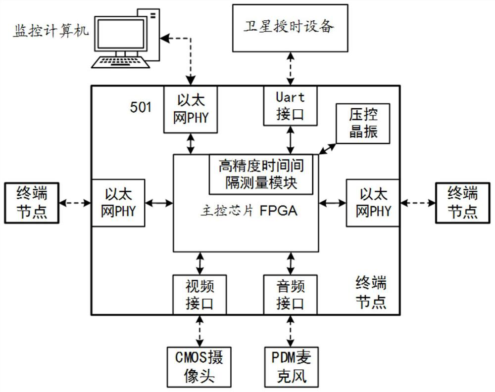
[0024] Each terminal node can realize time synchronization through the following methods: receiving satellite timing data output by satellite timing equipment; according to satellite timing data, carry out master-slave identification on each terminal node in the topology network, and determine the master node and slave node; according to the preset time Configure the table to synchronize time between the master node and the slave node.

[0025] Further, the determination of the master node and the slave node can be realized in the following manner: judging whether a terminal n...

Embodiment 2

[0037] The following is an example of time-triggered audio and video synchronous presentation of 16 terminal nodes.

[0038] As mentioned above, the topological network system is composed of satellite timing equipment, terminal nodes, audio and video acquisition equipment and monitoring computer. The audio and video signals collected by the audio and video acquisition equipment connected to 16 terminal nodes can be displayed synchronously on the monitoring computer in real time. The frame rate of the video signal is 15fps, and the picture pixel size is 320*240; the audio signal adopts the pulse width of 1.2MHz sampling rate Density modulation signal PDM transmission, using digital sampling filter on the monitoring computer side to realize transcoding from PDM to PCM standard audio format, and finally output 16bit audio with a sampling rate of 40KHz.

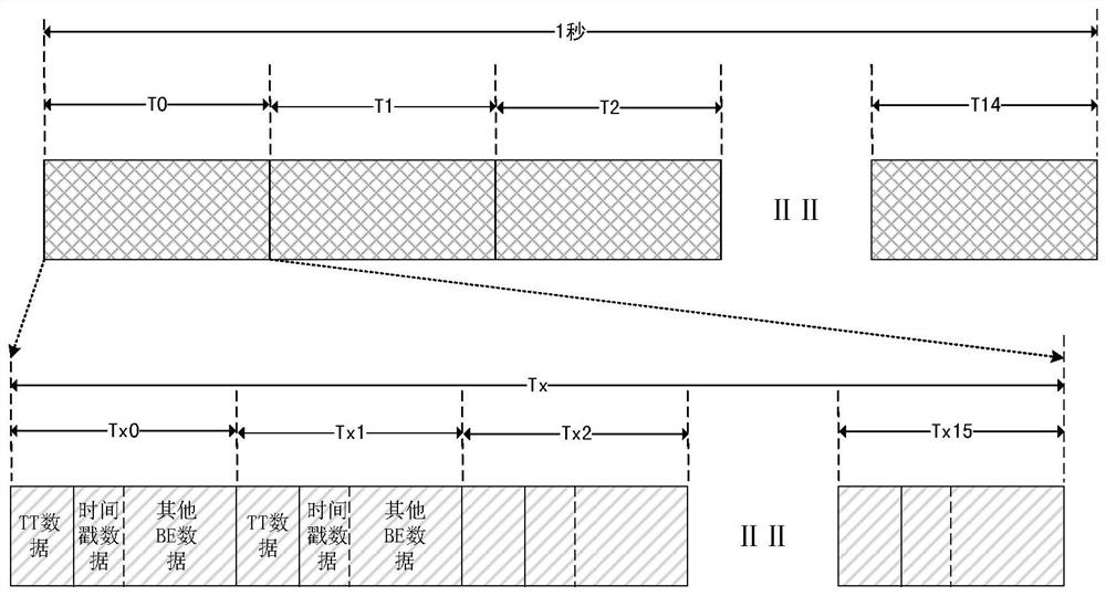
[0039] The data transmitted throughout the network includes video data, audio data, instructions and time stamp data, etc. The...


PUM


Abstract

The invention discloses a multi-node audio and video information synchronous sharing display method, comprising: performing time synchronization on each terminal node in the topology network according to satellite timing data output by satellite timing equipment; after all terminal nodes complete time synchronization, each According to the communication protocol specification, the terminal node starts the synchronous collection and buffering of audio and video data at a predetermined unified time; when any terminal node receives the monitoring command, it forwards the buffered audio and video data to the monitoring computer; the monitoring computer forwards all The audio and video data are classified and stored in the video cache queue and the audio cache queue; the audio data and video data in the video cache queue and the audio cache queue are decoded in sequence according to the queue order, and output for playback. The invention realizes synchronous sharing and display of multi-node audio and video information.

Description

technical field [0001] The invention relates to the technical field of communication, in particular to a method for synchronously sharing and displaying multi-node audio and video information. Background technique [0002] For strong real-time and high-safety control systems, the real-time and deterministic communication between nodes is the key to the realization of the system. Message communication protocols based on event-triggered message synchronization and scheduling are commonly used in general network processing modules. Many studies have shown that time-triggered solutions have greater advantages for high-reliability systems. Time Triggered Architecture (TTA) system and Event Triggered Architecture (Event Triggered Architecture, ETA) system have different working principles. Time triggering performs signal control according to the time process, while the control signal of event triggering is based on the occurrence of an event (such as an interruption). The basic...

Claims


Application Information

Patent Timeline
Patent Type & Authority Patents(China)
IPC IPC(8): H04J3/06H04N5/04
CPCH04J3/0661H04N5/04
Inventor 弓飞黄小华
Owner BEIJING HANGXING MACHINERY MFG CO LTD
Learn More