PVC pipeline conveying clamp for sewage discharge

A technology for pipeline transportation and sewage discharge, which is applied in transportation and packaging, multi-axis trolleys, trolley accessories, etc. problems, to achieve uniform force, avoid uneven force, and improve the effect of installation firmness

Active Publication Date: 2020-04-07
福建泉州业德弗科技有限公司
View PDF16 Cites 0 Cited by
  • Summary
  • Abstract
  • Description
  • Claims
  • Application Information

AI Technical Summary

Problems solved by technology

[0005] Aiming at the problems in the prior art, the object of the present invention is to provide a PVC pipe conveying fixture for sewage discharge, which solves the problem of bundling multiple PVC pipes together with ropes or strapping tapes in the process of conveying and transferring PVC pipes, which makes it easier for PVC pipes The outer wall is extruded, resulting in uneven force on the outer wall of the PVC pipe, causing the outer wall of the PVC pipe to be squeezed and deformed, which affects the technical problems of production, processing and later construction.

Method used


Image

  • PVC pipeline conveying clamp for sewage discharge
  • PVC pipeline conveying clamp for sewage discharge
  • PVC pipeline conveying clamp for sewage discharge

Examples


Embodiment 1

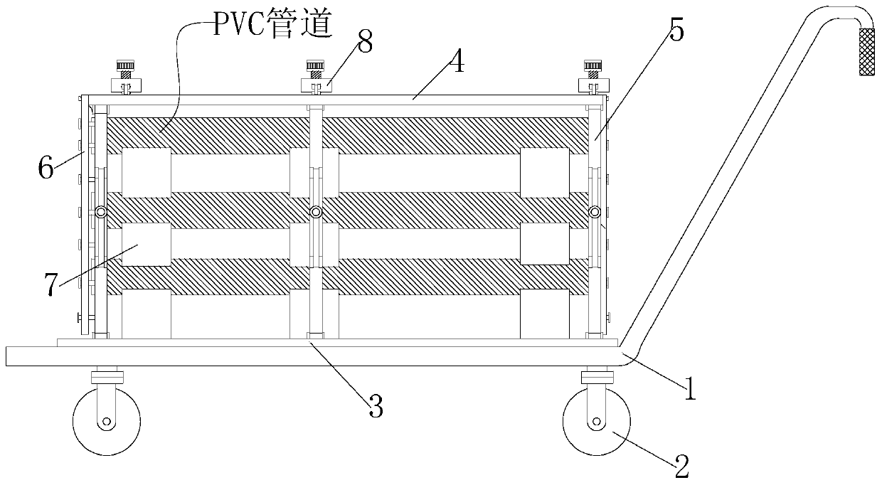
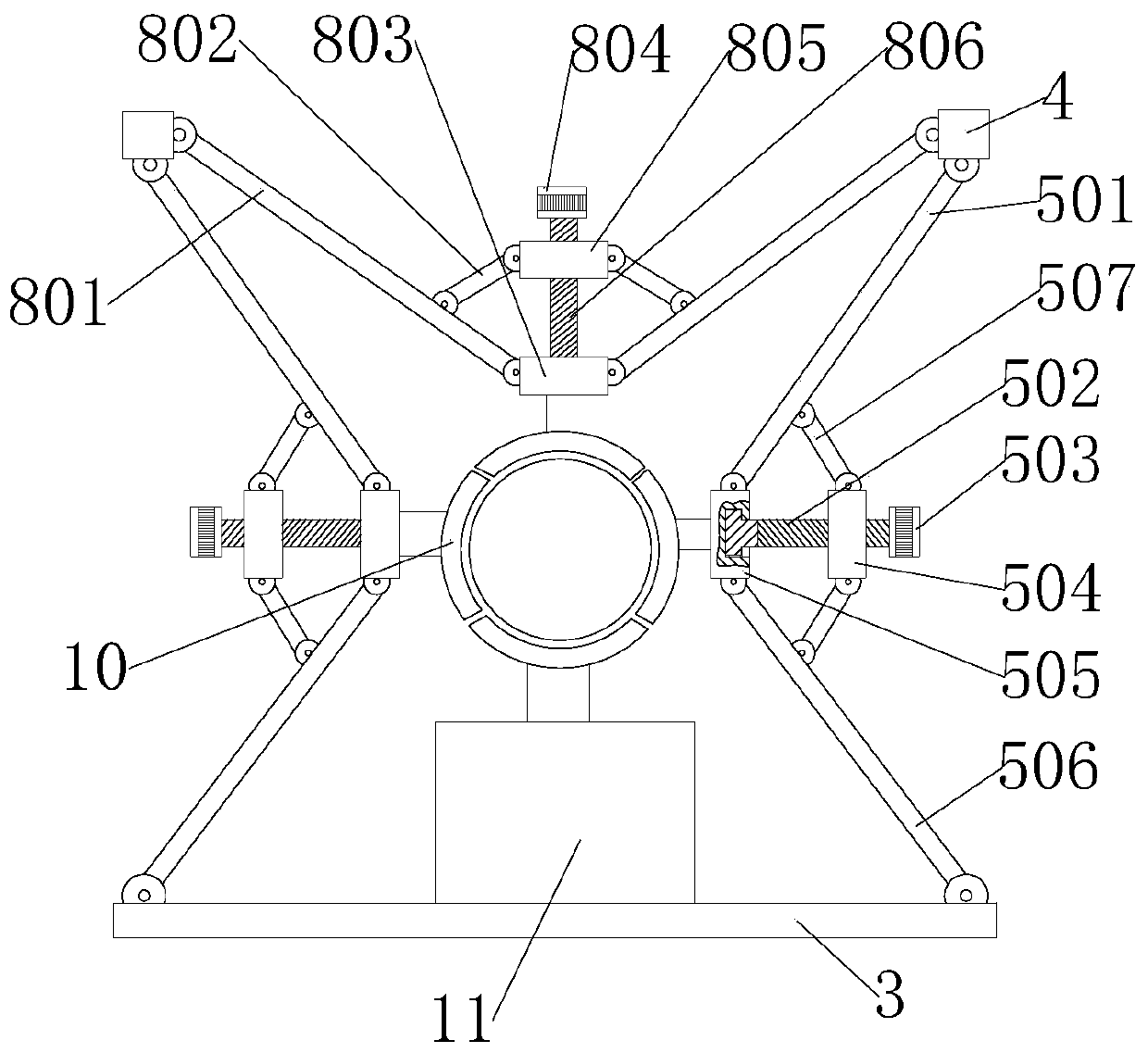
[0035] see figure 1 as well as Figure 3-Figure 6 , is a schematic diagram of the overall structure of a PVC pipe conveying fixture for sewage discharge, a PVC pipe conveying fixture for sewage discharge, including a base 3, a top fixing plate 4, a side connecting rod 5, and a top connecting rod 8, and the PVC pipe conveying fixture for sewage discharge The pipeline conveying fixture is mainly composed of base 3, side connecting rod 5 and top connecting rod 8 spliced ​​end to end. The two adjacent side connecting rods 5 on the side are equally spaced, and the top of the side connecting rods 5 on each side is hinged with a vertically installed top fixing rod 4, and a top connecting rod 8 is hinged between the top fixing rods 4 on both sides. A plurality of top connecting rods 8 are installed in the middle of the top fixing plates 4 on both sides at equal distances; The connecting rod 5 and the top connecting rod 8 bind the PVC pipes, the bottom end of the base 3 is equipped w...

Embodiment 2

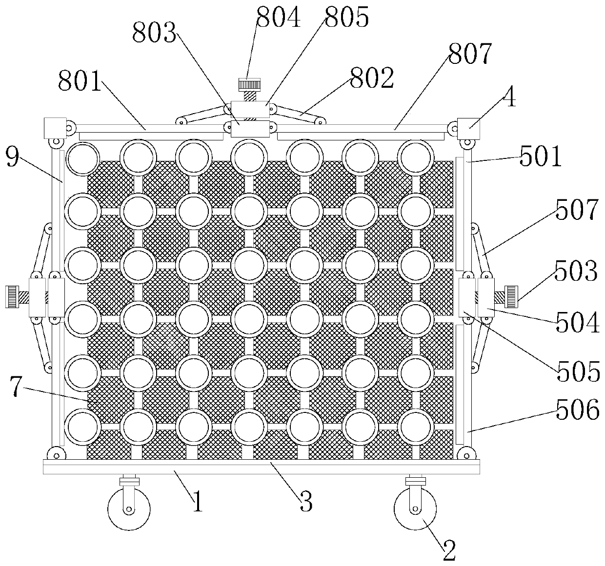
[0053] see figure 1 and figure 2 , is a schematic diagram of the overall structure of another PVC pipeline conveying fixture for sewage discharge. This embodiment has the same content as the above-mentioned embodiment 1, and the same will not be described in this embodiment. The specific difference is that :

[0054] The bottom end of each first hinged seat 505 is equipped with jaws 10, the bottom end of each second hinged seat 803 is equipped with jaws 10, and the top of base 3 is equipped with a square bottom fixed seat 11, the bottom fixed seat The top of 11 is equipped with clamping jaw 10.

[0055] The bottom end of each first hinge seat 505 is provided with a threaded hole, and the bottom end of each second hinge seat 803 is provided with a threaded hole. The plate is provided with a concave arc surface, and the convex surface of the clamping jaw 10 is provided with a cylindrical rod, and the outer surface of the cylindrical rod is provided with threads, and the clam...


PUM


Abstract

The invention discloses a PVC pipeline conveying clamp for sewage discharge and relates to the technical field of sewage treatment equipment. The clamp comprises a base, a top fixing plate, a side connecting rod and a top connecting rod, the PVC pipeline conveying clamp for sewage discharge is mainly formed by splicing the base, side connecting rods and a top connecting rod end to end, the base isa horizontally-arranged square plate, the multiple side connecting rods are symmetrically hinged to the front side and the rear side of the top end of the base, and every two adjacent side connectingrods on each side are arranged at equal intervals. A disc-shaped magnetic block is embedded into the circle center of the top end of each connecting column; every two adjacent cushion blocks are connected through a magnetic block. The connecting columns of every two adjacent cushion blocks are rapidly attracted through the magnetic blocks, the operation efficiency during installation is improved,the cushion blocks can be rapidly disassembled conveniently when a PVC pipeline is taken out of the clamp, and the installation operation simplicity of the cushion blocks is improved.

Description

technical field [0001] The invention relates to the technical field of sewage treatment equipment, in particular to a PVC pipe delivery fixture for sewage discharge. Background technique [0002] A pipe is a tubular material with a cavity inside, and the cross-section of the pipe has a circular, square, triangular, polygonal, etc. structure. [0003] PVC pipe, commonly known as hard polyvinyl chloride pipe, is made of polyvinyl chloride resin, stabilizer, lubricant, etc., and is extruded by hot pressing. It is the earliest plastic pipe that has been developed and applied. PVC-U pipe has strong corrosion resistance, Easy to bond, low price, hard texture, but due to the leakage of PVC-U monomer and additives, it is only suitable for water supply systems with a delivery temperature not exceeding 45°C. Plastic piping is used in applications for drainage, waste water, chemicals, heating and cooling fluids, food, ultrapure liquids, slurries, gases, compressed air and vacuum syste...

Claims


Application Information

Patent Timeline
Patent Type & Authority Applications(China)
IPC IPC(8): B62B3/04B62B5/00
CPCB62B3/04B62B5/0006B62B2202/02
Inventor 陈思霆
Owner 福建泉州业德弗科技有限公司
Why Eureka
Try Eureka