Logistics cargo fixing device
A logistics and cargo technology, applied in the direction of internal accessories, etc., can solve the problems of connecting hook and decoupling, and achieve the effect of convenient operation, good anti-drop performance, and improved convenience.
- Summary
- Abstract
- Description
- Claims
- Application Information
AI Technical Summary
Problems solved by technology
Method used
Image

Examples
Embodiment 1
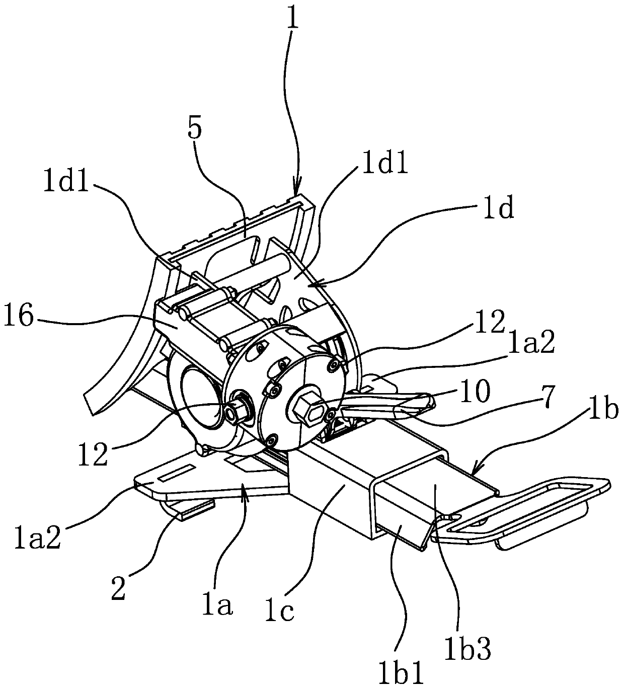
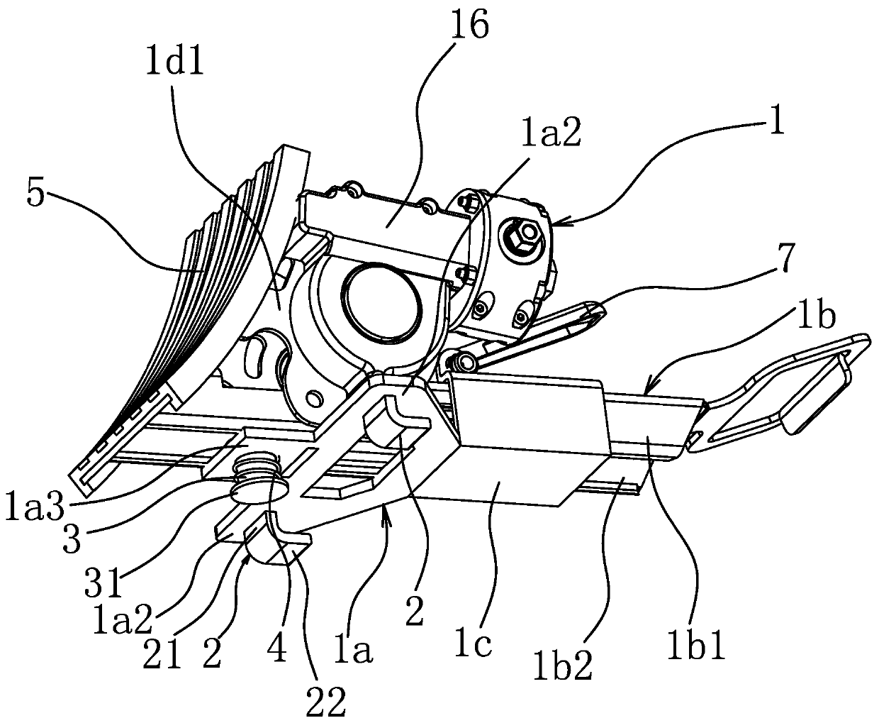
[0037] Such as figure 1 with figure 2 As shown, the logistics cargo container includes a base body 1 on which a cargo fixing structure for positioning the cargo is provided, and a connecting hook 2 is provided on the bottom surface of the base body 1 . Specifically, the seat body 1 includes a bottom plate 1a, a bar-shaped connecting piece 1b connected to the upper part of the bottom plate 1a, and a reel support 1d. The shape connector 1b is fixedly connected. The bottom of the seat body 1 is also provided with a pressing element that can expand and contract vertically, and the pressing element can rebound downward by itself without external force after shrinking upward.
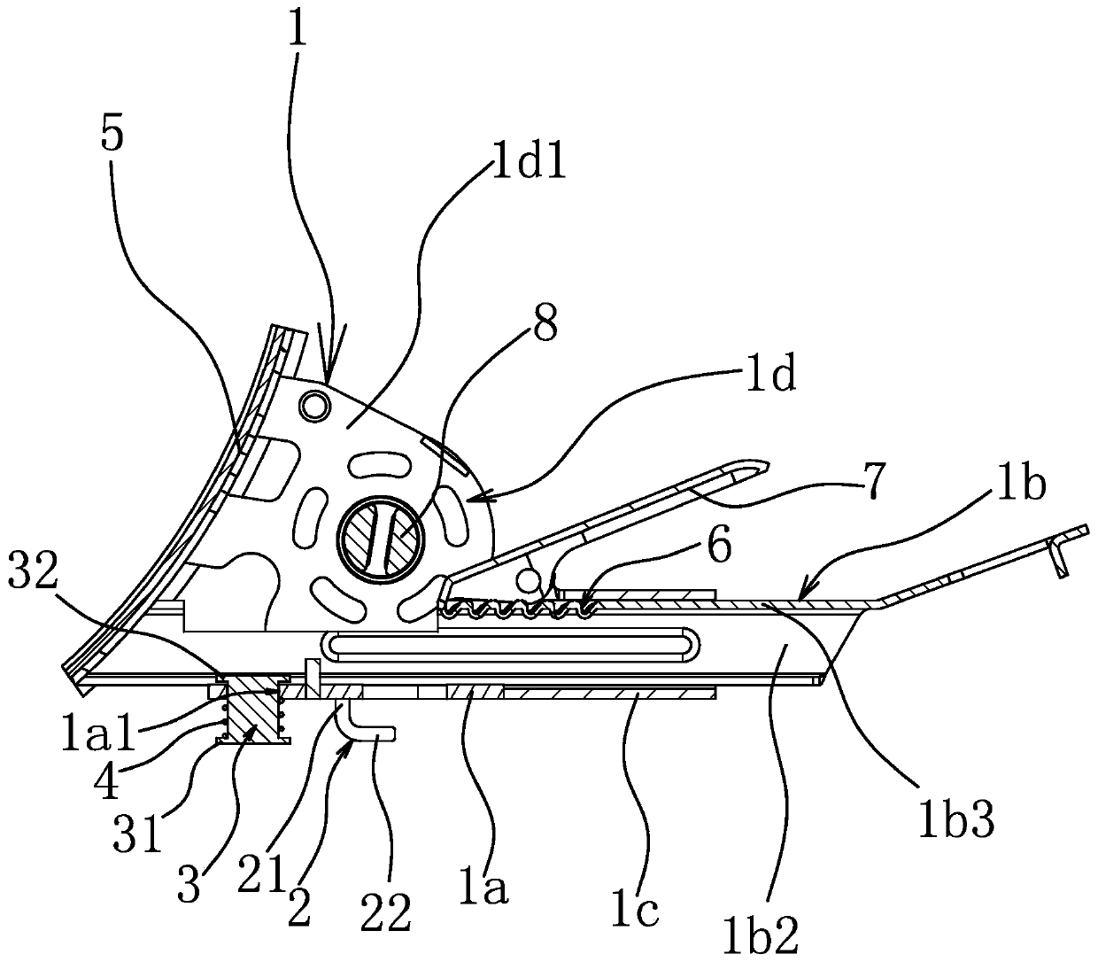
[0038] Such as image 3 with Figure 4 As shown, the pressing element includes a telescopic pin 3 vertically pierced on the bottom plate 1 a and an elastic member 4 acting on the telescopic pin 3 and used to press down the telescopic pin 3 . Specifically, the bottom plate 1a is provided with a mounting ...
Embodiment 2
[0046] The structure and principle of this embodiment are basically the same as that of Embodiment 1, the difference is that: Figure 7 As shown, the pressing element is an elastically deformable rubber pad 13 , and the lower end surface of the rubber pad 13 is lower than the top surface of the hooking portion 22 of the connecting hook 2 . The lower end surface of the rubber pad 13 is lower than the top surface of the hooking portion 22 of the connecting hook 2 to ensure that the rubber pad 13 can be compressed during the hooking process of the connecting hook 2 . After the rubber pad 13 is compressed, it also has a tendency to rebound by itself, so the effect of improving the detachment resistance of the connecting hook 2 can also be achieved in the same way.
Embodiment 3
[0048] The structure and principle of this embodiment are basically the same as that of Embodiment 1, the difference is that: Figure 8 As shown, the pressing element is a tower spring 14, the axis of the tower spring 14 is perpendicular to the bottom plate 1a and the small diameter end of the tower spring 14 is fixedly connected to the bottom plate 1a. During the hooking process of the connecting hook 2, the tower spring 14 is compressed so that the connecting hook 2 is stably hooked in the hooking hole. And the large-diameter end of tower spring 14 is downward, not only can tower spring 14 be compressed stably, but also has larger contact area between it and hole plate 15 surfaces after being compressed, tower spring 14 and hole There will also be greater frictional resistance between the hole plates 15 , so as to better prevent the base body 1 from moving freely and improve the anti-detachment performance of the connecting hook 2 .
PUM
 Abstract
Description
Claims
Application Information
 - R&D
- Intellectual Property
- Life Sciences
- Materials
- Tech Scout
- Unparalleled Data Quality
- Higher Quality Content
- 60% Fewer Hallucinations
Browse by: Latest US Patents, China's latest patents, Technical Efficacy Thesaurus, Application Domain, Technology Topic, Popular Technical Reports.
© 2025 PatSnap. All rights reserved.Legal|Privacy policy|Modern Slavery Act Transparency Statement|Sitemap|About US| Contact US: help@patsnap.com