A flywheel housing and flywheel mounting sling and method of using the same

A flywheel housing and flywheel technology, applied in the field of flywheel housing and flywheel installation spreader, can solve the problems of difficult operation, hidden safety hazards, and high labor intensity of workers, achieve strong versatility, reduce labor intensity and operation difficulty, and improve production efficiency effect

Active Publication Date: 2022-07-22
DONGFENG AUTOMOBILE COMPANY
View PDF0 Cites 0 Cited by
  • Summary
  • Abstract
  • Description
  • Claims
  • Application Information

AI Technical Summary

Problems solved by technology

[0003] At present, when assembling the flywheel shell and the flywheel, different simple spreaders are generally used. The flywheel shell is lifted first, and then the flywheel is lifted. The spreader needs to be switched back and forth. Security risks

Method used


Image

  • A flywheel housing and flywheel mounting sling and method of using the same
  • A flywheel housing and flywheel mounting sling and method of using the same
  • A flywheel housing and flywheel mounting sling and method of using the same

Examples


Embodiment 1

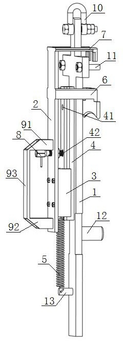
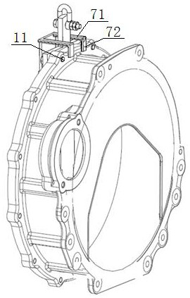
[0043] see figure 1 , figure 2 , a flywheel housing and a flywheel mounting sling, comprising a support plate 1, a limit plate 2, a slider 3, a latch 8, and the upper part of the front of the support plate 1 is provided with a flywheel that matches the fixing holes of the periphery of the flywheel shell The shell limit support pin 11, the middle part of the front of the support plate 1 is provided with the center limit pin 12 of the flywheel which is matched with the center through hole of the flywheel, the middle part and the lower part of the back of the support plate 1 are respectively provided with a longitudinal slideway 4 and a transverse connecting rod 13 , the longitudinal slideway 4 is provided with a hoisting positioning hole 41 and a locking hole 42, the lifting positioning hole 41 is located above the locking hole 42, and one side of the slider 3 is slidingly matched with the longitudinal slideway 4, The other side of the sliding block 3 is fixedly connected with...

Embodiment 2

[0048] The difference from Example 1 is:

[0049] see figure 1 , the spreader also includes a handle 9 and a lifting ring 10. The handle 9 includes an upper connecting plate 91 located above the latch 8, a lower connecting plate 92 located below the latch 8, and a hand grip 93. The upper connecting plate 91, One end of the lower connecting plate 92 is fixedly connected to the back of the limiting plate 2, and the other ends of the upper connecting plate 91 and the lower connecting plate 92 are fixedly connected to the upper and lower ends of the handle bar 91 respectively, and the suspension ring 10 is an inverted U-shaped structure. , its lower end is fixedly connected with the top end of the support plate 1 through a locking nut.


PUM


Abstract

A flywheel shell and a flywheel mounting sling, comprising a support plate, a limit plate and a slider, the upper part of the front of the support plate is provided with a flywheel shell limit support pin matched with a fixing hole in the periphery of the flywheel shell, and the front of the support plate is provided with a flywheel shell limit support pin. The center of the flywheel is provided with a limit pin in the center of the flywheel, which is matched with the center through hole of the flywheel, and the middle of the back of the support plate is provided with a longitudinal slideway. The lower end of the front is fixedly connected, and the bottom end is fixedly connected to the back of the support plate through the return spring. The upper part of the limit plate is provided with a flywheel shell limit upper claw located above the flywheel shell limit support pin, and the flywheel shell limit support pin. The upper jaw of the flywheel limit between the center limit pin of the flywheel and the flywheel. The design not only improves production efficiency, but also has strong versatility, safety and reliability.

Description

technical field [0001] The invention belongs to the technical field of automobile engines, and in particular relates to a flywheel housing, a flywheel mounting sling and a use method thereof. Background technique [0002] The flywheel housing is installed at the rear end of the engine, effectively connecting the engine and the gearbox, and plays the role of connecting the body, protection and carrier. The flywheel is a wheel-shaped energy storage part that is installed at the rear end of the crankshaft and has a large moment of inertia to enable the engine to rotate at a uniform speed. The flywheel shell is generally made of gray cast iron and the weight is about 10-20kg; the flywheel is generally made of ductile iron, and the weight accounts for a considerable part of the total weight of the engine (about 1 / 10 for the four-cylinder engine, and 1 / 20 to 1 / 15 for the six-cylinder engine). ). During the assembly process of the engine, the flywheel housing and flywheel need to...

Claims


Application Information

Patent Timeline
Patent Type & Authority Patents(China)
IPC IPC(8): F16F15/315B66C1/42B66C13/08
Inventor 江波韩晶晶金海涛杨帅王长学杨立学李炜炜刘文奇
Owner DONGFENG AUTOMOBILE COMPANY
Why Eureka
Try Eureka