An electroplating time adjustment device for automatic electroplating equipment

A technology for electroplating equipment and time adjustment, which is applied to electrolytic components, electrolytic processes, cells, etc., can solve the problems of inflexible use, etc., and achieve the effects of easy promotion, simplified structure and wide application range.

Active Publication Date: 2022-02-11
漳州市福美鑫新材料科技有限公司
View PDF12 Cites 0 Cited by
  • Summary
  • Abstract
  • Description
  • Claims
  • Application Information

AI Technical Summary

Problems solved by technology

[0004] The above-mentioned existing technical solutions have the following defects: because each piece of pendant is indirectly connected to the circular track used to drive each piece of pendant up and down through roller sliding, therefore, each piece of workpiece in the same processing tank The electroplating time is consistent (during the electroplating process, the walking device will still drive the workpiece to walk slowly, so the electroplating time of the workpiece is equal to the quotient of the length of the treatment tank and the speed of the hanger. The electroplating time is the same), but in actual production, because of the different size and shape of different workpieces, different workpieces have different requirements for electroplating. Therefore, the electroplating time of different workpieces in the same treatment tank is relatively long There is a big difference, but the above-mentioned technology obviously cannot realize the function of electroplating different workpieces for different durations in the same treatment tank, resulting in that the workpieces to be electroplated in the same batch can only be of the same type. If different workpieces need to be electroplated, only Divide it into two batches for electroplating or use multiple automatic electroplating equipment for electroplating separately, which is not flexible enough to use. Therefore, there are still relatively large use defects in the prior art as mentioned above

Method used


Image

  • An electroplating time adjustment device for automatic electroplating equipment
  • An electroplating time adjustment device for automatic electroplating equipment
  • An electroplating time adjustment device for automatic electroplating equipment

Examples


Embodiment 1

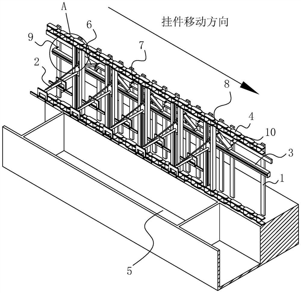
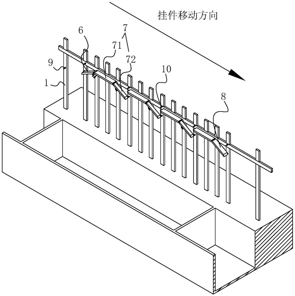
[0047] Example 1: Combining figure 1 and figure 2 As shown, it is an electroplating time adjustment device for automatic electroplating equipment disclosed by the present invention. The electroplating time adjustment device is located above one of the treatment tanks 5, and the electroplating time adjustment device includes a frame set on the automatic electroplating equipment 1 and above the constant track 7 so that part of the hanging parts 2 will not move down with the circular track 3. The constant track 7 is set on the frame 1 of the automatic electroplating equipment and is located on the side where the constant track 7 is opposite to the moving direction of the hanging parts 2. One end is used to transfer the pendant 2 on the circular track 3 to the upward track assembly 6 on the constant track 7 and is arranged on the frame 1 of the automatic electroplating equipment and is positioned on the end of the constant track 7 away from the upward track assembly 6 to It is u...

Embodiment 2

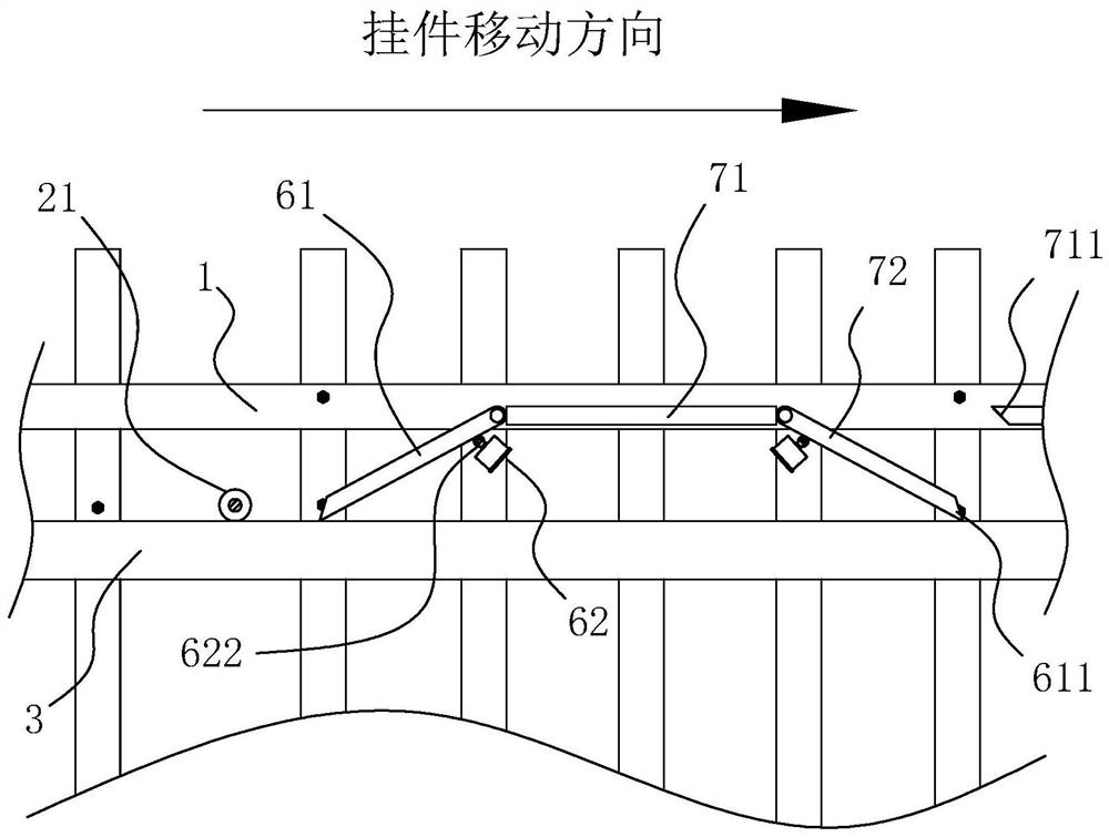
[0058] Embodiment two: if Figure 7 As shown, the difference from Embodiment 1 is that several groups of guide assemblies 12 are arranged on the frame 1 and located at the end of each sub-rail 71 close to the upper rail 61, and the upper rail 61 and each connecting rail 72 are arranged horizontally. And it is vertically slidably connected to the guide assembly 12 , and the driving device 62 is configured as a motor screw transmission mechanism 623 for driving the upward rail 61 or the connecting rail 72 to go up and down.

[0059] Specifically, each group of guide assemblies 12 includes two guide rails 121 arranged vertically and parallel to each other. When the up track 61 or the connecting track 72 lifts up and down, the two track slide rails can play the guiding effect of stably supporting the two ends of the upper and lower tracks or the connecting track 72 .

[0060] Specifically, the motor screw transmission mechanism 623 includes a common motor 624 whose body is fixed ...


PUM


Abstract

The present invention relates to an electroplating time adjustment device for automatic electroplating equipment, the technical field of electroplating equipment, which includes setting on the frame of automatic electroplating equipment and above the constant track so that part of the pendant will not go down with the circular track The moving constant track, which is set on the rack of the automatic electroplating equipment and is located on the end of the constant track opposite to the moving direction of the pendant, is used to transfer the pendant on the circular track to the upward track assembly on the constant track, and is set on the automatic electroplating equipment. On the rack of the equipment and on the end of the constant track away from the ascending track assembly, it is used to retransfer the pendant moved to the end of the constant track to the descending track on the circular track. The invention has the effect of improving the flexibility of automatic electroplating equipment.

Description

technical field [0001] The invention relates to the technical field of electroplating equipment, in particular to an electroplating time adjustment device for automatic electroplating equipment. Background technique [0002] The electroplating process is a method of covering a conductor with a layer of metal using the principle of electrolysis. Electroplating refers to a surface processing method in which the cations of the pre-plated metal in the plating solution are deposited on the surface of the base metal by electrolysis with the base metal to be plated as the cathode in a salt solution containing pre-plated metal to form a coating. . The performance of the coating is different from that of the base metal and has new characteristics. According to the function of the coating, it is divided into protective coating, decorative coating and other functional coatings. During electroplating, the plated metal or other insoluble materials are used as the anode, and the workpi...

Claims


Application Information

Patent Timeline
Patent Type & Authority Patents(China)
IPC IPC(8): C25D21/10C25D21/12
CPCC25D21/10C25D21/12
Inventor 彭兴发李道俊苏杰
Owner 漳州市福美鑫新材料科技有限公司
Why Eureka
Try Eureka