Compressor pump body and compressor
A compressor pump and cylinder technology, applied in the field of compressors, can solve the problems of increased oil discharge rate of compressors, affecting compression efficiency, large side exhaust resistance, etc., and achieves reduction of exhaust resistance, simple structure, and reduced The effect of resistance
- Summary
- Abstract
- Description
- Claims
- Application Information
AI Technical Summary
Problems solved by technology
Method used
Image
Examples
Embodiment 1
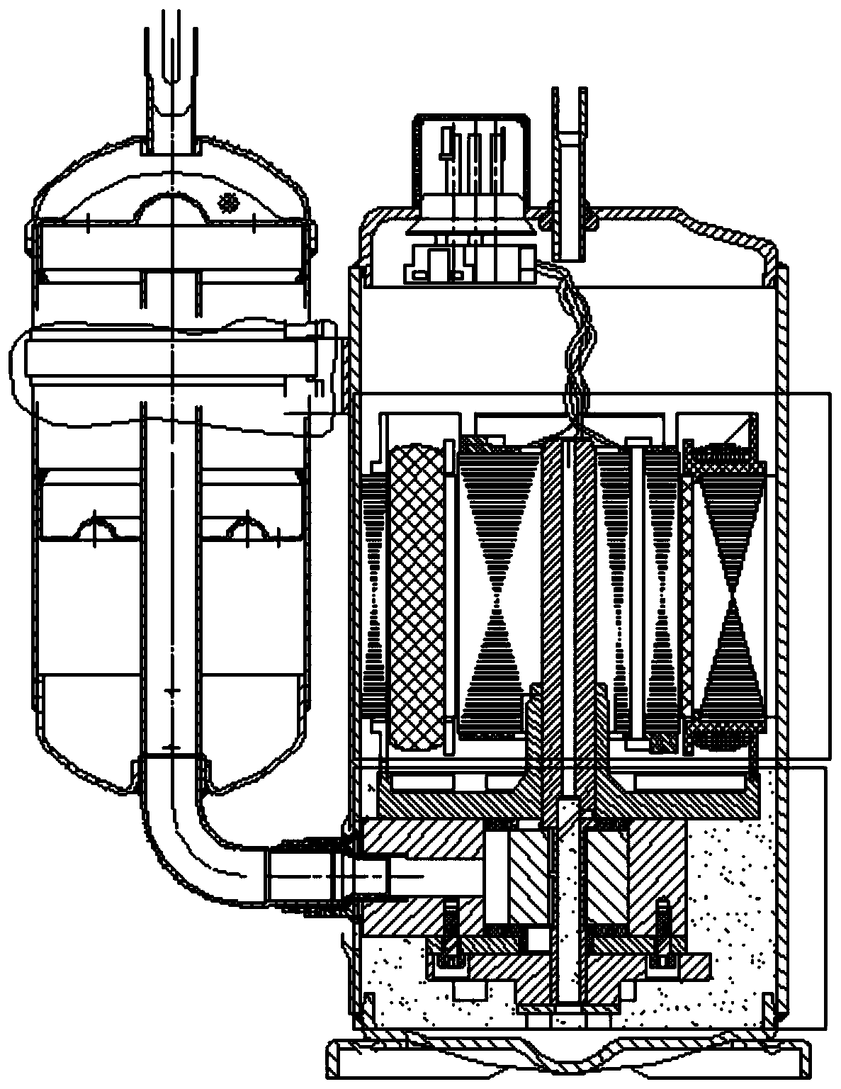
[0037] like Figure 1-Figure 3 As shown, the exhaust ports 71 of the cylinder 5 are all opened on the side of the cylinder 5 at present. During the operation of the compressor, the exhaust port 71 is immersed in the refrigerating oil, and the refrigerant of the compressor is directly discharged into the refrigerating oil on the side, which will cause large exhaust resistance and serious overcompression, which will affect the performance and compression efficiency of the compressor; at the same time, it will As a result, the oil discharge rate of the compressor increases, which affects the energy efficiency of the air conditioning system.
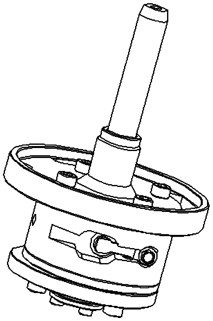
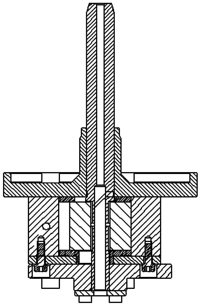
[0038] A compressor pump body, such as Figure 4 and Figure 5 As shown, it includes a rotating shaft 1, a piston 2, a flange 3, a limiting plate 4 and a cylinder 5; the cylinder 5 is provided with a piston 2 and a rotating shaft 1, and the cylinder 5 and the rotating shaft 1 rotate around their respective centers. The suction channel 6 a...
Embodiment 2
[0045] On the basis of Example 1, such as Figure 5 , Figure 9-Figure 10As shown, the flange 3 includes two flanges 3 , the cross-sectional area of the upper flange 3 is larger than that of the lower flange 3 , and the upper flange 3 is provided with an exhaust hole 74 . The limiting plate 4 includes two limiting plates 4 , the cross-sectional area of the upper limiting plate 4 is larger than that of the lower limiting plate 4 , and the upper limiting plate 4 is provided with an exhaust hole 74 . The second exhaust passage 8 includes the exhaust hole 74 on the exhaust groove 73, the exhaust hole 74 of the upper flange 3 and the exhaust hole 74 of the upper limit plate 4, two exhaust holes 74 It is collinear with the center line of the exhaust hole 74 on the exhaust groove 73 . The cross-sectional area of the upper limiting plate 4 is smaller than the cross-sectional area of the upper flange 3 .
[0046] During assembly, the structure of the flange 3 and the limitin...
Embodiment 3
[0048] On the basis of Embodiment 1 and Embodiment 2, the corners of the cover plate 9 are provided with screw holes, and the positions of the screw holes are consistent with the positions of the preset mounting holes on the cylinder 5. 5 connected together. A sealing structure is provided between the cover plate 9 and the cylinder 5 .
[0049] The structure of the cover plate 9 is simple, easy to manufacture, and low in use cost; the cover plate 9 separates the exhaust groove 73 from the refrigerated oil; it is used in conjunction with a gasket, and the isolation effect is good; the upper end of the exhaust groove 73 is provided with an exhaust hole 74 to limit Vent holes 74 are provided at the corresponding positions of the plate 4 and the upper flange 3 to form the second exhaust passage 8, and the traditional side exhaust method is improved to the upper exhaust method.
[0050] The compressor discharges the refrigerant through the exhaust port 71. The refrigerant first en...
PUM
 Abstract
Description
Claims
Application Information
 - R&D
- Intellectual Property
- Life Sciences
- Materials
- Tech Scout
- Unparalleled Data Quality
- Higher Quality Content
- 60% Fewer Hallucinations
Browse by: Latest US Patents, China's latest patents, Technical Efficacy Thesaurus, Application Domain, Technology Topic, Popular Technical Reports.
© 2025 PatSnap. All rights reserved.Legal|Privacy policy|Modern Slavery Act Transparency Statement|Sitemap|About US| Contact US: help@patsnap.com


