
Low-temperature pipeline mounting structure

A pipeline installation and pipeline technology, which is applied in the direction of pipeline protection, pipeline protection through heat insulation, expansion compensation device for pipelines, etc., can solve the problems of no liquefied water collection and diversion mechanism, the influence of other structures of liquefied water, etc., and achieve maintenance Easy installation, avoid cracks, and avoid impact effects

Pending Publication Date: 2020-04-07
常州威华电子股份有限公司
View PDF0 Cites 0 Cited by
  • Summary
  • Abstract
  • Description
  • Claims
  • Application Information

AI Technical Summary

Problems solved by technology

[0004] The purpose of the present invention is to provide a low-temperature pipeline installation structure to solve the problem that most of the existing low-temperature pipeline installations in the above-mentioned background technology are directly fixed on external objects through hoops, and there is no collection and diversion of liquefied water on the outer surface of the pipeline. mechanism, it is easy to cause the problem that liquefied water will affect the rest of the structure

Method used


Image

  • Low-temperature pipeline mounting structure
  • Low-temperature pipeline mounting structure
  • Low-temperature pipeline mounting structure

Examples


Embodiment Construction

[0018] The following will clearly and completely describe the technical solutions in the embodiments of the present invention with reference to the accompanying drawings in the embodiments of the present invention. Obviously, the described embodiments are only some, not all, embodiments of the present invention.

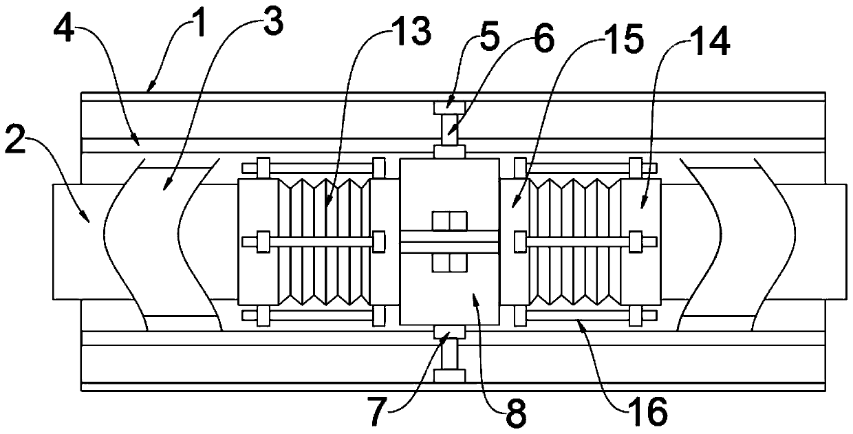
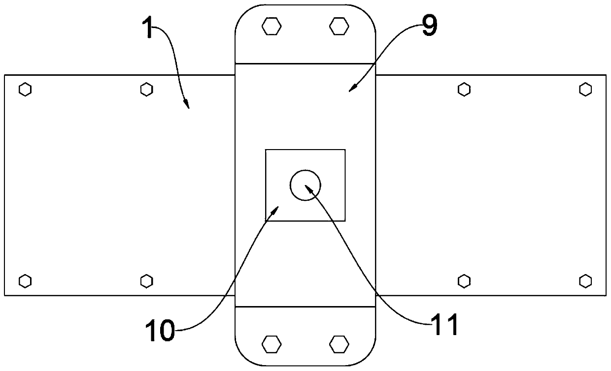
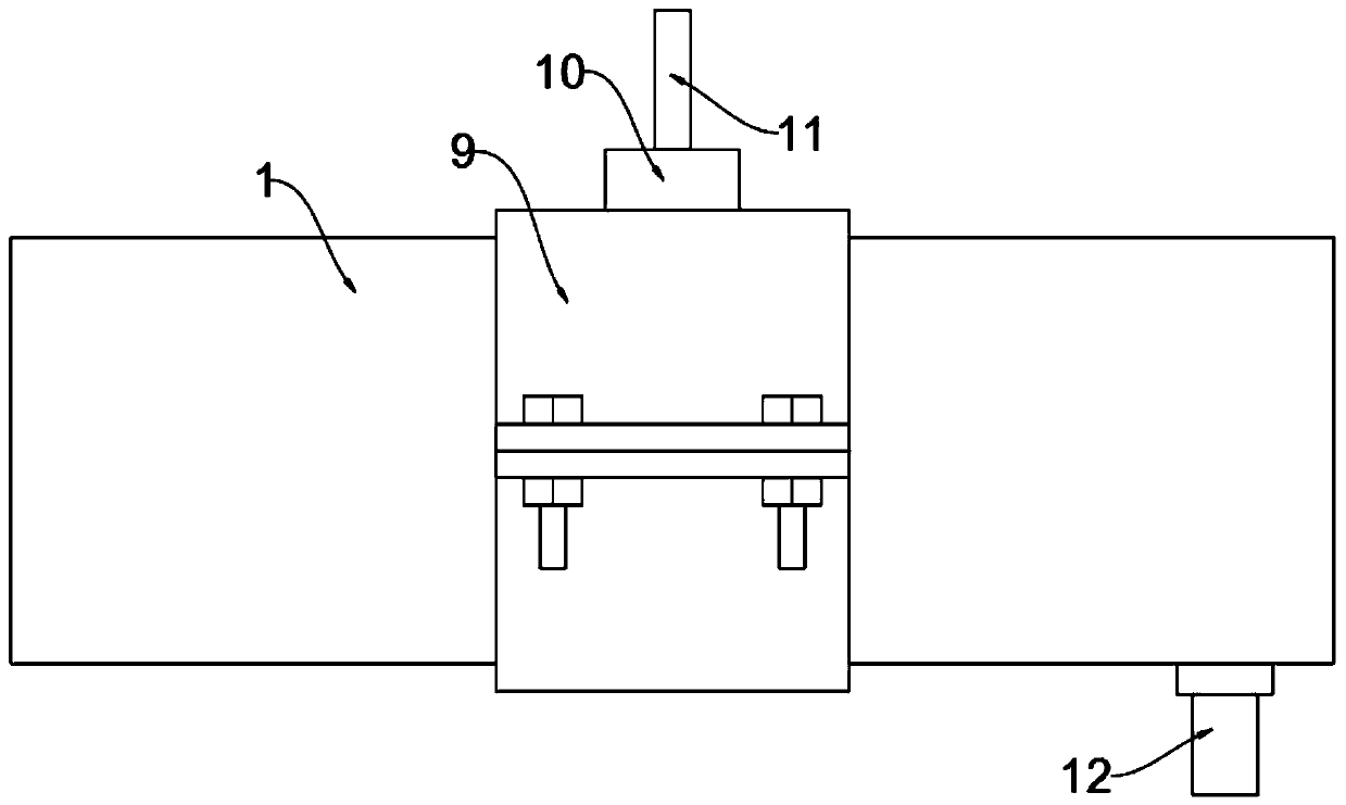
[0019] see Figure 1-3 , an embodiment provided by the present invention: a low-temperature pipeline installation structure, including a protective shell 1, a low-temperature pipeline 2 is arranged inside the protective shell 1, and the outer surface of the low-temperature pipeline 2 is wrapped with water-absorbent cotton 3, and the protective shell The inner bottom of the body 1 is provided with a drainage groove 4, and the absorbent cotton 3 is located directly above the drainage groove 4, and the outer surface of the bottom end of the protective shell body 1 is fixedly connected with a drainage pipe 12, and the water inlet end of the drainage pipe 12 is connected w...


PUM


Abstract

The invention discloses a low-temperature pipeline mounting structure, relates to the field of low-temperature pipeline mounting, and aims to solve the problems that most existing low-temperature pipelines are directly fixed on external objects through hoops, and liquefied water on the outer surfaces of the pipelines is not collected and guided by a mechanism, so that the liquefied water easily affects other structures. A low-temperature pipeline is arranged in a protective outer housing; the outer surface of the low-temperature pipeline is wrapped with absorbent cotton; a drainage groove is formed in the bottom end of the interior of the protective outer housing; the absorbent cotton is located right above the drainage groove; a drainage pipe is fixedly connected to the outer surface of the bottom end of the protective outer housing; and the water inlet end of the drainage pipe is communicated with the interior of the drainage groove.

Description

technical field [0001] The invention relates to the field of low-temperature pipeline installation, in particular to a low-temperature pipeline installation structure. Background technique [0002] With the development of society, more and more fields need to use cryogenic pipes for the delivery of cryogenic fluids, such as long-distance delivery of cold air or long-distance delivery of cooling liquid for industrial equipment and so on. [0003] Most of the existing low-temperature pipeline installations are directly fixed on external objects through hoops. There is no collection and diversion mechanism for the liquefied water on the outer surface of the pipeline, which may easily cause liquefied water to affect other structures. In order to collect liquefied water , to avoid the impact of other structures; therefore, the market urgently needs to develop a low-temperature pipeline installation structure to help people solve existing problems. Contents of the invention [...

Claims


Application Information

Patent Timeline
IPC IPC(8): F16L59/135F16L51/03F16L21/06F16L55/07
CPCF16L21/06F16L51/028F16L51/03F16L55/07F16L59/135
Inventor 刘国杰
Owner 常州威华电子股份有限公司
Learn More