
Excitation circuit and electromagnetic flowmeter

An excitation circuit and excitation current technology, which is applied in the application of electromagnetic flowmeters to detect fluid flow, volume/mass flow generated by electromagnetic effects, and measure flow/mass flow, etc., and can solve problems such as power increase.

Active Publication Date: 2022-03-25
YAMATAKE HONEYWELL CO LTD
View PDF7 Cites 0 Cited by
  • Summary
  • Abstract
  • Description
  • Claims
  • Application Information

AI Technical Summary

Problems solved by technology

Therefore, as the excitation current increases, the electric power consumed in vain by the constant current circuit increases, and heat generation of the excitation circuit becomes a problem.

Method used


Image

  • Excitation circuit and electromagnetic flowmeter
  • Excitation circuit and electromagnetic flowmeter
  • Excitation circuit and electromagnetic flowmeter

Examples


Embodiment approach

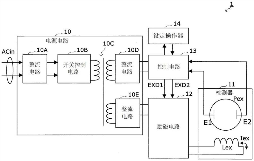
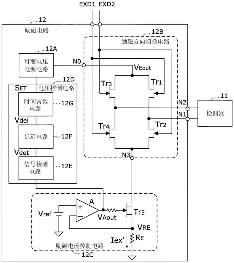
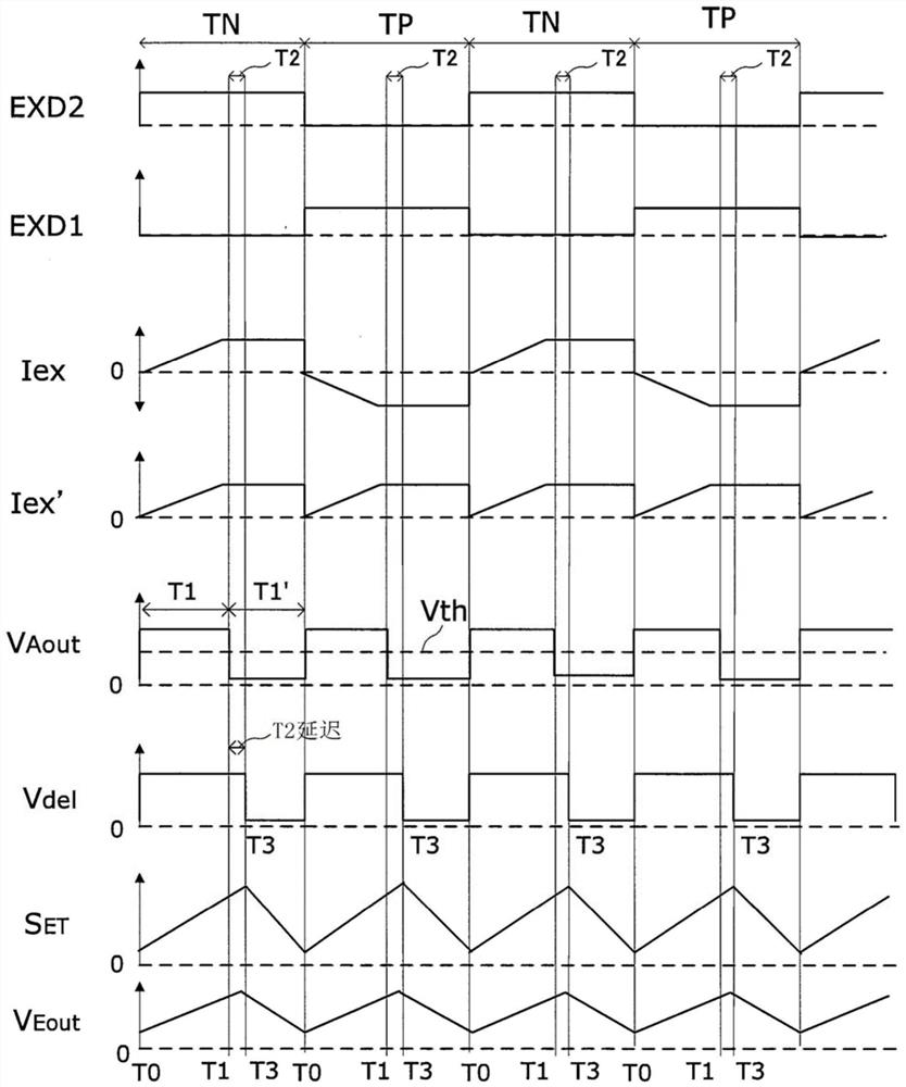
[0032] Below, refer to Figure 1 to Figure 3 Preferred embodiments of the present invention will be described in detail.

[0033] First, refer to figure 1 and figure 2 , the exciting circuit 12 according to the embodiment of the present invention and the electromagnetic flowmeter 1 using the exciting circuit will be described.

[0034] [Electromagnetic Flowmeter]

[0035] like figure 1 As shown, the electromagnetic flowmeter 1 of this embodiment includes a power supply circuit 10 , a detector 11 , an excitation circuit 12 , a control circuit 13 , and a setting operator 14 .

[0036] Here, the detector 11 has: a measuring tube Pex for flowing the fluid to be measured; an exciting coil Lex arranged near the measuring tube Pex, receiving the supply of an exciting current Iex, and generating A magnetic field perpendicular to the flow direction of the fluid flowing inside the measuring tube Pex; and a pair of detection electrodes E1, E2, which are perpendicular to the flow dire...


PUM


Abstract

An object of the present invention is to provide an excitation circuit and an electromagnetic flowmeter capable of changing an excitation voltage according to the characteristics of an excitation coil and the magnitude of an excitation current. The excitation circuit (12) has: a variable voltage power supply circuit (12A), which can output an excitation voltage (V Eout ), and according to the voltage control signal (S ET ) to change the excitation voltage V Eout The size of the switch circuit (12B), which switches the excitation voltage (V Eout ) and apply the field voltage to the field coil (Lex); field current control circuit (12C), which includes: generating a current control signal based on the magnitude of the field current supplied to the field coil (V Aout ) current control signal generation circuit, and a control element (Tr5) that controls the magnitude of the excitation current based on the current control signal to energize the excitation coil with a prescribed constant current; and a voltage control circuit (12D), which generates a voltage control circuit (12D) based on the current control signal. signal and input it to the variable voltage power supply circuit.

Description

technical field [0001] The present invention relates to an electromagnetic flowmeter for measuring the flow rate of a fluid in various process systems, and an excitation circuit for supplying an excitation current to an excitation coil of the electromagnetic flowmeter. Background technique [0002] Generally, an electromagnetic flowmeter is equipped with a detector, which includes: an exciting coil that generates a magnetic field in a direction perpendicular to the flow direction of fluid flowing in the measuring tube; and a pair of detecting electrodes that are arranged in the measuring tube and The flow direction of the fluid and the direction of the magnetic field are arranged to face each other in a direction perpendicular to each other. In such an electromagnetic flowmeter, the flow rate of a fluid flowing in a measuring tube is measured based on an electromotive force generated between detection electrodes when the fluid flows in a magnetic field generated by an exciti...

Claims


Application Information

Patent Timeline
Patent Type & Authority Patents(China)
IPC IPC(8): G01F1/60G01F1/58
CPCG01F1/582G01F1/60
Inventor 卫藤有文
Owner YAMATAKE HONEYWELL CO LTD
Learn More