Engine hood dynamic fatigue analysis method

An engine cover and analysis method technology, applied in computer-aided design, geometric CAD, design optimization/simulation, etc., can solve the problems of prolonging the engine cover optimization design cycle, heavy workload, and long time consumption, and shorten the development and design time Effect

Active Publication Date: 2020-04-07
CHONGQING CHANGAN AUTOMOBILE CO LTD
View PDF10 Cites 3 Cited by
  • Summary
  • Abstract
  • Description
  • Claims
  • Application Information

AI Technical Summary

Problems solved by technology

However, this method has at least the following defects: Compared with the engine cover system, the calculation of the whole vehicle model is large and time-consuming, and the workload unrelated to the calculation of the engine cover is large, which prolongs the optimal design cycle of the engine cover.

Method used


Image

  • Engine hood dynamic fatigue analysis method
  • Engine hood dynamic fatigue analysis method
  • Engine hood dynamic fatigue analysis method

Examples


Embodiment Construction

[0023] The present invention will be further described below in conjunction with accompanying drawing.

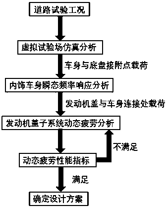
[0024] Such as figure 1 As shown, a dynamic fatigue analysis method of engine cover includes the following steps:

[0025] Step A, load decomposition:

[0026] In order to verify the durability and reliability of the vehicle, it is necessary to conduct different road tests according to different models, that is, to run the vehicle on some roads, such as pebble roads and Belgian roads, for a certain period of time at a certain speed and with a counterweight. In order to speed up the load extraction, these working conditions can be simulated and analyzed on a virtual test site, and the loads of the corresponding road body and chassis attachment points can be obtained respectively.

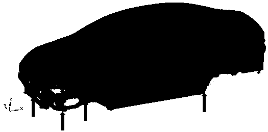
[0027] Step B. Finite element transient frequency response analysis of the interior body model:

[0028] Prepare the interior body finite element mesh model, such as figure 2 As shown, accord...


PUM


Abstract

The invention discloses an engine hood dynamic fatigue analysis method, which comprises the following steps of: A, performing virtual test field simulation analysis according to a reliability road test working condition to obtain a load of an attachment point of a vehicle body and a chassis; b, according to the load obtained in the step A, carrying out transient frequency response analysis on thebasis of a CAE method, and extracting force and torque of the connection point of the engine hood and the vehicle body; c, according to the force and torque of the connection point of the engine coverand the vehicle body obtained in the step B, carrying out dynamic fatigue analysis of an engine cover system based on a CAE method, and obtaining fatigue performance; d, judging whether the fatigue performance of the engine hood is qualified or not by taking the design requirement as a standard; if so, entering the step F; otherwise, entering the step E; e, optimizing the structural design of theengine cover and the arrangement mode of buffer blocks, and entering the step C; and F, adopting the engine cover structure. The invention provides an efficient engine hood dynamic fatigue analysis method.

Description

technical field [0001] The invention belongs to the technical field of computer-aided design of automobiles, and in particular relates to a dynamic fatigue analysis method of an engine cover. Background technique [0002] When the car is running, under the dual excitation of the engine and the road, the engine cover is always in a relatively complex vibration environment. If the design of the engine cover cannot meet the requirements of dynamic fatigue performance, it will have a great impact on the safety and acoustic roughness (NVH performance) of the car. Therefore, it is necessary to use the CAE method in the design stage of the engine cover. Fatigue durability analysis. [0003] When performing dynamic fatigue analysis on the engine cover, it is first necessary to place it in the interior car body to obtain the acceleration history of each attachment position of the car body and chassis in the road test, and then use the load cycle iterative method to calculate the fat...

Claims


Application Information

Patent Timeline
Patent Type & Authority Applications(China)
IPC IPC(8): G06F30/23G06F30/15G06F119/04
CPCY02T90/00
Inventor 谢敏捷曾小利赵松王华
Owner CHONGQING CHANGAN AUTOMOBILE CO LTD
Why Eureka
Try Eureka