
A system and method for a live working robot to automatically change working tools

A technology for live work and work tools, applied in the system field of live work robots automatically replacing work tools, can solve problems such as pinching operators, tools falling, complex structure, etc., to achieve compact structure, improve replacement efficiency, and improve work efficiency Effect

Active Publication Date: 2022-02-22
STATE GRID INTELLIGENCE TECH CO LTD
View PDF0 Cites 0 Cited by
  • Summary
  • Abstract
  • Description
  • Claims
  • Application Information

AI Technical Summary

Problems solved by technology

But its disadvantages are: live working tools have various forms and complex structures, and the weight of a single live working tool can reach 5-10kg. It is inconvenient for a single person to grasp with one arm. The tightening stability is poor, which leads to low efficiency of live work, and there is a risk of tools falling and pinching workers
[0004] It can be seen that there is still a large technical deficiency in the high-voltage live working robot in the existing research technology, which has seriously restricted the practical application and promotion of the live working robot in the power grid.

Method used


Image

  • A system and method for a live working robot to automatically change working tools
  • A system and method for a live working robot to automatically change working tools
  • A system and method for a live working robot to automatically change working tools

Examples


Embodiment 1

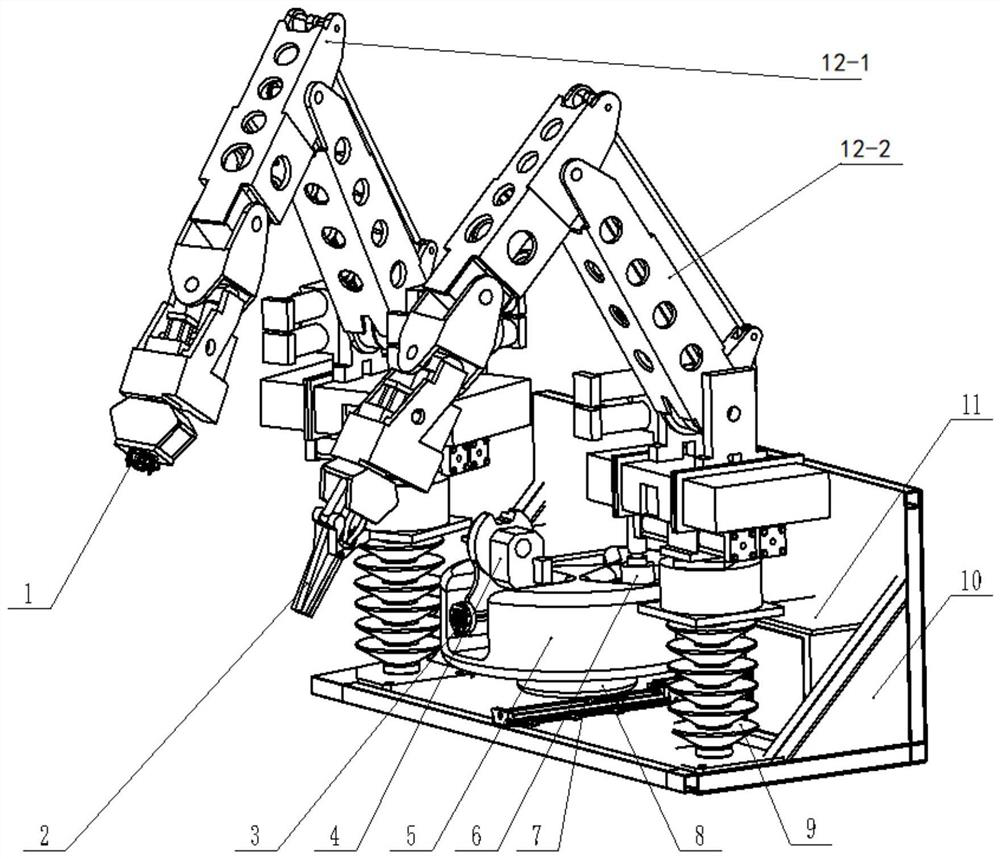
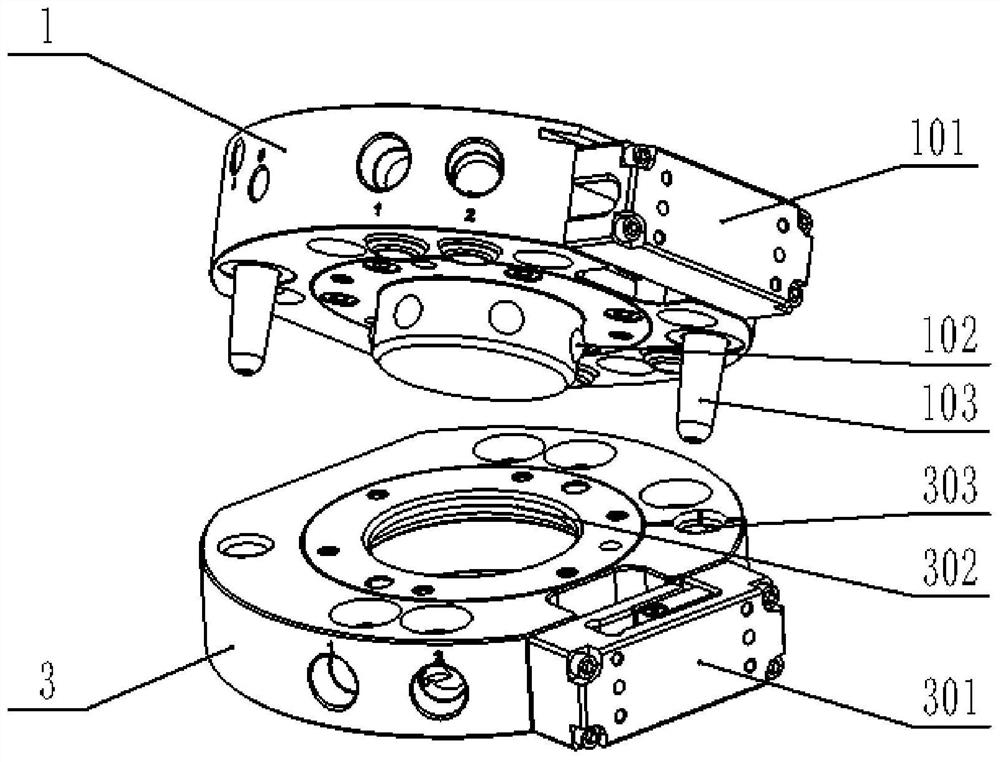
[0028] In one or more embodiments, a system for automatically changing tools of a live working robot is disclosed, including: a live working platform 10, on which a working robot arm 12-1 and a tool changing mechanism are respectively arranged; The tool replacement mechanism includes a rotating part and a tool magazine 5 arranged on the rotating part; at least two live working tools are arranged in the tool magazine 5, and each live working tool is provided with a working robot arm 12- 1 One-touch fittings that match the end fittings.

[0029] Exemplary, see figure 1 , the live working platform 10 is respectively equipped with a working robot arm 12-1, a wire clamping robot arm 12-2, a screw guide rail pair 7, a rotating mechanism 8 and a tool magazine 5;

[0030] Wherein, the operation manipulator 12-1 and the wire clamping manipulator 12-2 are connected to the live work platform 10 through the post insulator 9, and one work manipulator 12-1 is installed on each post insulat...

Embodiment 2

[0046] In one or more embodiments, a method for automatic tool replacement of a live working robot is disclosed, including three processes of tool selection, tool positioning and tool replacement.

[0047] 1) Tool selection

[0048] Put the used tools into the tool library 5 sequentially according to the process requirements, code each tool, and select the tool according to the coding of the tool library 5 . Select tool by coding during operation, and the used tool is put back in the original tool storehouse 5 .

[0049] 2) Tool positioning

[0050] According to the instruction received to replace the working tool, match the corresponding working tool through coding;

[0051] Rotate the tool magazine 5 to rotate the corresponding operating tool to the set position;

[0052] 5-position locking of the tool magazine;

[0053] Start the tool replacement mechanism, and drive the motor to rotate forward or reverse to return to the original position. Send the tool selection comm...


PUM


Abstract

The invention discloses a system and method for automatically changing working tools by a live working robot, comprising: a live working platform, on which a working mechanical arm and a tool changing mechanism are respectively arranged; the changing tool mechanism includes a rotating part and a A tool magazine arranged on the rotating part; the tool magazine is provided with at least two live working tools, and each live working tool is provided with a quick-change joint matching the end joint of the working mechanical arm. The invention adopts the disc-type quick-change joint to replace the tool, realizes the locking and positioning of the tool through quick plugging and unplugging, and can realize the independent and quick replacement function of the working tool of the live working robot.

Description

technical field [0001] The invention relates to the technical field of high-voltage live working robots, in particular to a system and method for automatically changing working tools for a live working robot. Background technique [0002] The statements in this section merely provide background information related to the present invention and do not necessarily constitute prior art. [0003] Distribution network live work robots are mainly used to complete tasks such as stripping insulated wires, disconnecting drain wires with power, removing foreign objects, replacing drop insurance, pruning branches, replacing cross arms, and replacing transformers. In order to improve the automation level and safety of live work, To reduce the labor intensity of operators and the personal threat of strong electromagnetic fields to operators, since the 1980s, domestic and foreign power companies have successively carried out research on live working robots. Operators work on live working p...

Claims


Application Information

Patent Timeline
Patent Type & Authority Patents(China)
IPC IPC(8): B25J11/00B25J19/00
CPCB25J11/00B25J19/00
Inventor 司金保赵生传刘斌李明张婷婷许崇新田书然李启江刘波磊赵阅群周明亮林令臣闫同
Owner STATE GRID INTELLIGENCE TECH CO LTD
Learn More