Wood board edge banding device for table board production
A technology of edge banders and table boards, which is applied to other plywood/plywood appliances, wood processing appliances, household components, etc., and can solve the problems of energy consumption and inaccurate edge banding
- Summary
- Abstract
- Description
- Claims
- Application Information
AI Technical Summary
Problems solved by technology
Method used
Image

Examples
Embodiment 1
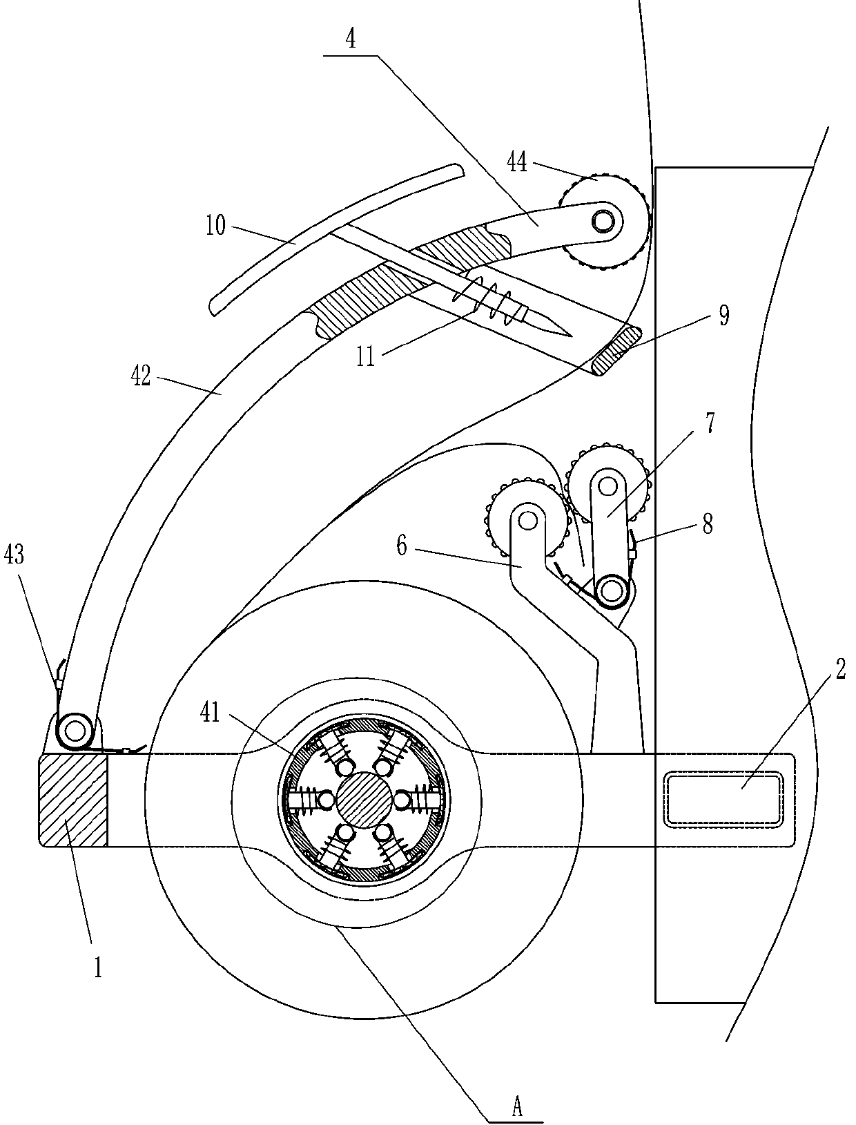
[0019] A wooden board edge bander for table board production, such as Figure 1-2 As shown, it includes an L-shaped plate 1, a guide roller 2, an adjustment device 3 and an edge banding device 4. The right side of the inner bottom of the L-shaped plate 1 is provided with a guide roller 2, and the upper left part of the L-shaped plate 1 is provided with an adjustment device. Device 3, the adjusting device 3 is used to adjust the gap between the device and the table board, the edge sealing device 4 is arranged in the middle of the L-shaped board 1, and the edge sealing device 4 is used to seal the table board.
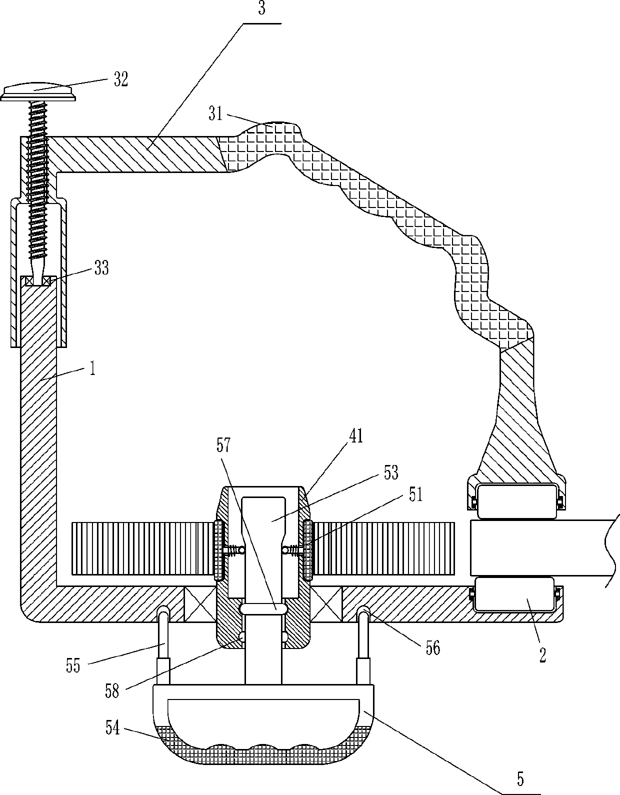
[0020] The adjustment device 3 includes a special-shaped plate 31, a threaded knob 32 and a bearing 33. The lower end of the left part of the special-shaped plate 31 is a square opening, and the special-shaped plate 31 is sleeved on the left part of the L-shaped plate 1 through the square opening. The guide roller 2 is provided in the way, the left part of the L-shaped p...
Embodiment 2
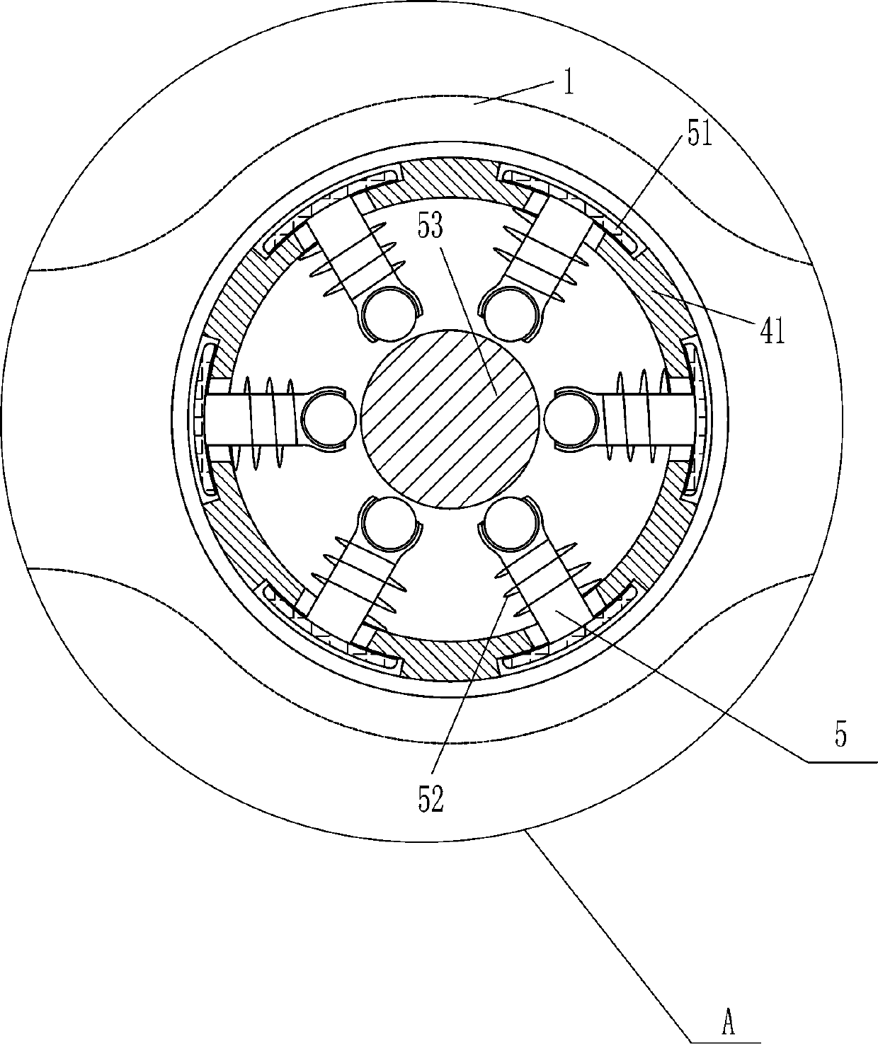
[0024] On the basis of Example 1, such as Figure 1-3 As shown, the fastening device 5 includes a T-shaped bar 51, a first spring 52, a special-shaped cylindrical block 53, a handle 54, an insertion rod 55 and a limit protrusion ring 57, and the hollow cylinder 41 is evenly spaced with T-shaped A rod 51, a first spring 52 is connected between the T-shaped rod 51 and the hollow cylinder 41, and a special-shaped cylindrical block 53 is slidably arranged in the hollow cylinder 41, and the T-shaped rod 51 contacts and cooperates with the special-shaped cylindrical block 53, The special-shaped cylindrical block 53 passes through the hollow tube 41, and a handle 54 is installed on the bottom of the special-shaped cylindrical block 53. Two inserting rods 55 are welded on the handle 54. Two card slots 56 are opened at the bottom of the L-shaped plate 1. The rod 55 cooperates with the clamping groove 56, and the special-shaped cylindrical block 53 is provided with a limiting raised rin...
Embodiment 3
[0027] On the basis of Example 2, such as figure 2 As shown, it also includes a fixed roller bar 6, a movable roller bar 7 and a second torsion spring 8, and the rear side of the right part of the L-shaped plate 1 is provided with a fixed roller bar 6 in a bolt-connected manner. A movable roller bar 7 is provided in a rotating manner, and the movable roller bar 7 is connected with the fixed roller bar 6 to be provided with a second torsion spring 8 .
[0028] It also includes a U-shaped frame 9, a T-shaped cutter 10 and a second spring 11. The inner side of the arc bar 42 is fixedly connected with the U-shaped frame 9, and the arc-shaped bar 42 is slidably provided with a T-shaped cutter 10. A second spring 11 is connected between the T-shaped cutter 10 and the arc bar 42 , and the T-shaped cutter 10 cooperates with the U-shaped frame 9 .
[0029] The operator peels off the release paper and places it between the fixed roller 6 and the movable roller 7. When the movable roll...
PUM
 Abstract
Description
Claims
Application Information
 - R&D Engineer
- R&D Manager
- IP Professional
- Industry Leading Data Capabilities
- Powerful AI technology
- Patent DNA Extraction
Browse by: Latest US Patents, China's latest patents, Technical Efficacy Thesaurus, Application Domain, Technology Topic.
© 2024 PatSnap. All rights reserved.Legal|Privacy policy|Modern Slavery Act Transparency Statement|Sitemap