Control method and system for wheel slipping
A technology of wheel slip and control method, applied in the field of wheel slip control methods and systems, can solve problems such as reducing driving experience, false alarms, etc., and achieve the effects of improving driving experience, improving safety, and preventing slipping
- Summary
- Abstract
- Description
- Claims
- Application Information
AI Technical Summary
Problems solved by technology
Method used
Image
Examples
Embodiment 1
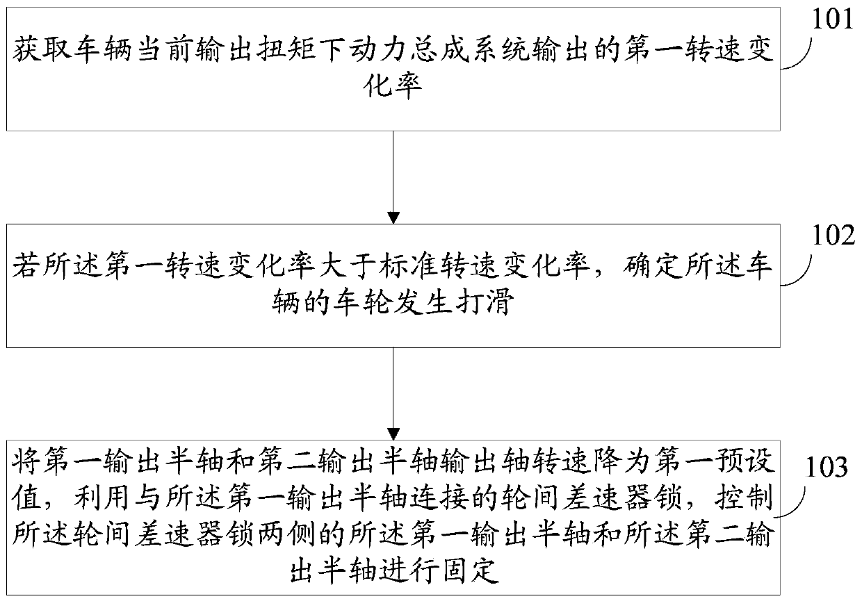
[0046] see figure 1 , figure 1 It is an example diagram of a wheel slip control method of the present application, the method comprising:
[0047] Step 101: Obtain the first rate of change of the rotational speed output by the powertrain system under the current output torque of the vehicle.
[0048] As an implementation manner, the first rate of change of rotational speed output by the vehicle powertrain system may be acquired through a sensor installed on the vehicle.
[0049] Step 102: If the first rate of change of rotational speed is greater than the standard rate of change of rotational speed, determine that the wheels of the vehicle are slipping.
[0050]As an implementation manner, the acquired rotational speed change rate output by the powertrain system under the current torque is compared with a standard rotational speed change rate, and if it is greater than the standard rotational speed change rate, it is determined that the wheels of the vehicle are slipping.
...
Embodiment 2
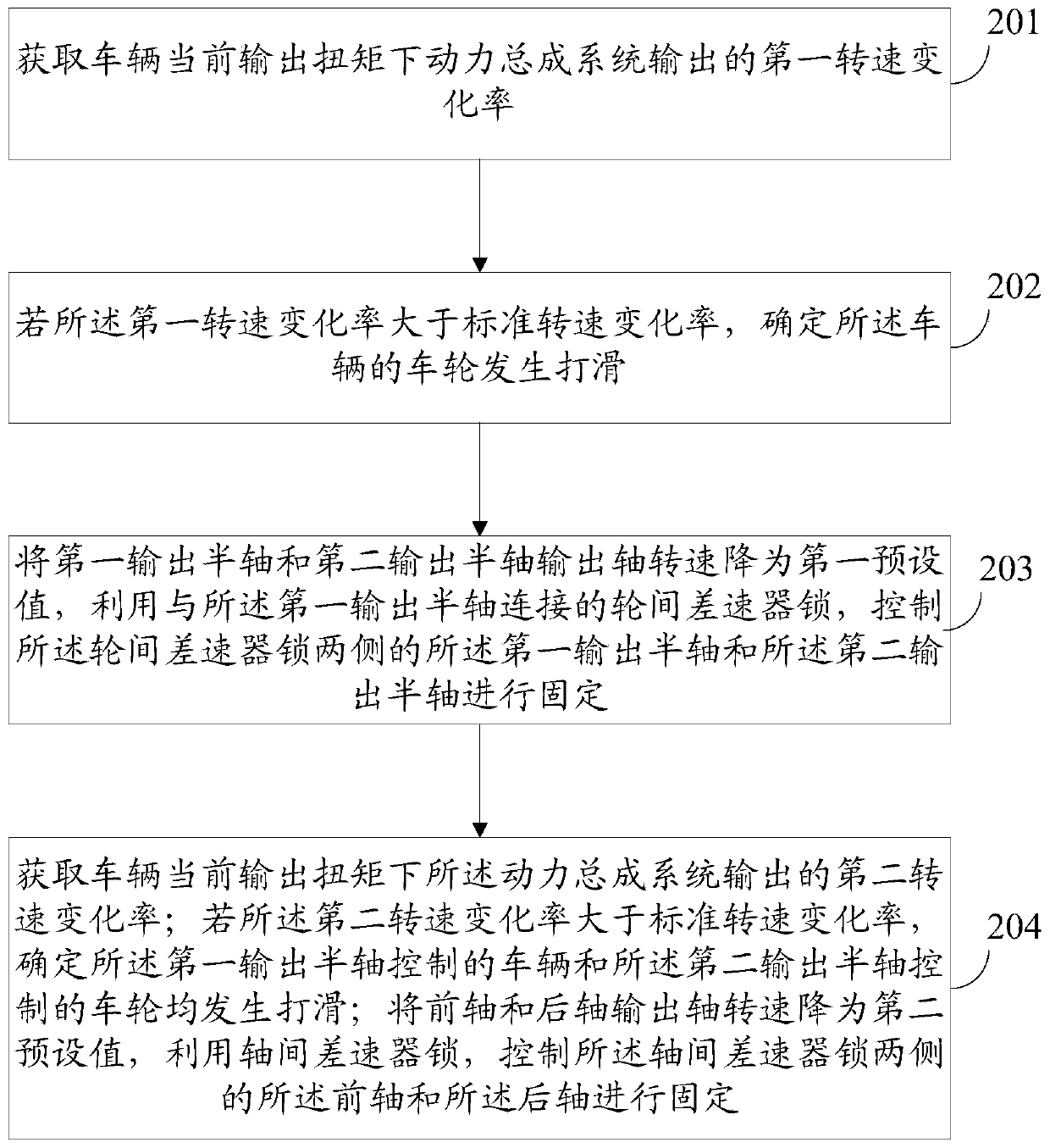
[0056] see figure 2 , figure 2 It is an example diagram of another wheel slip control method of the present application. The second embodiment of the present application is introduced on the basis of the first embodiment of the present application. The same or similar parts as the first embodiment of the present application are implemented in this application. It is not repeated in Example 2. The method includes:
[0057] Step 201-Step 203: Refer to Embodiment 1 of this application.
[0058] Step 204: Obtain the second rate of change of rotational speed output by the powertrain system under the current output torque of the vehicle; if the second rate of change of rotational speed is greater than the standard rate of change of rotational speed, determine the vehicle controlled by the first output axle shaft and the The wheels controlled by the second output axle shaft all slip; the output shaft speeds of the front axle and the rear axle are reduced to the second preset val...
Embodiment 3
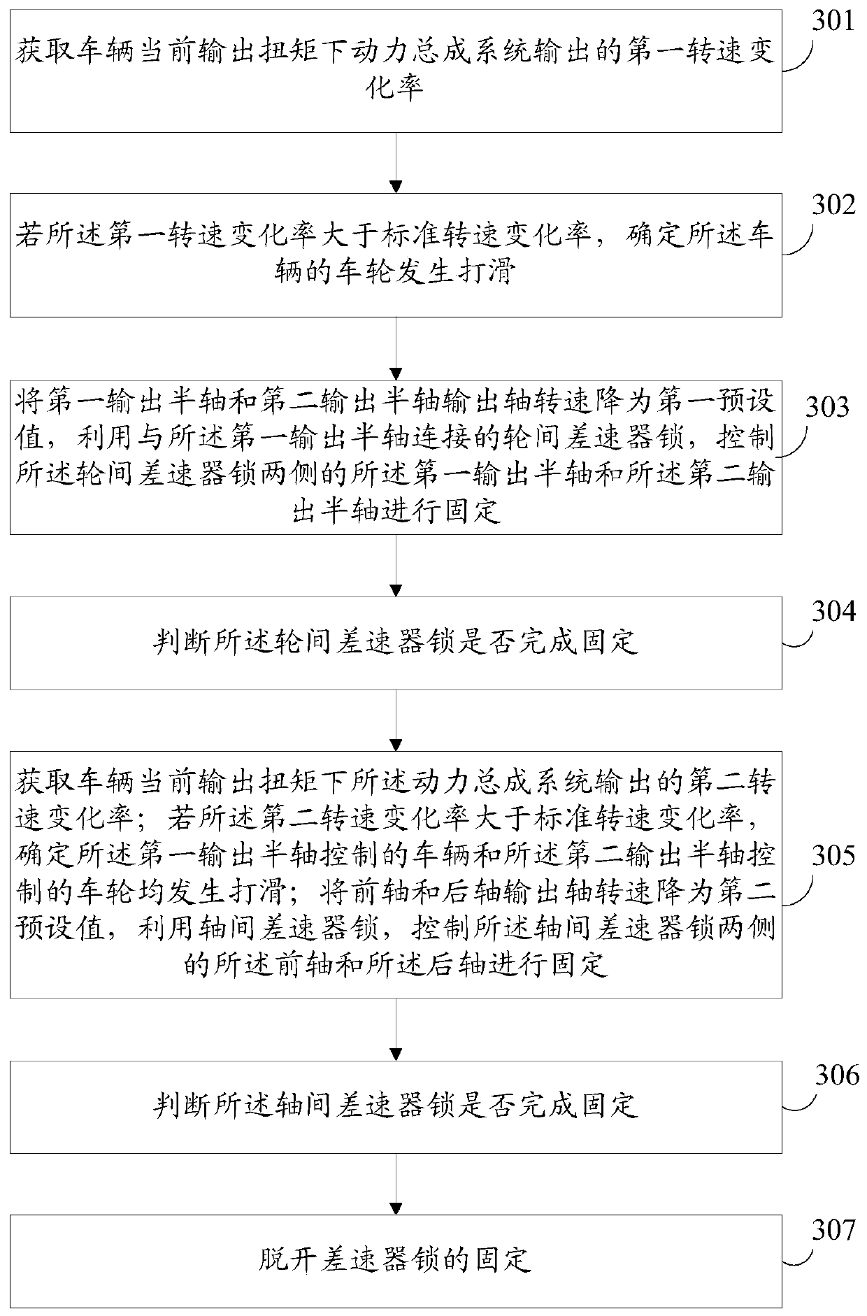
[0062] see image 3 , image 3 It is an example diagram of another wheel slip control method of the present application. The third embodiment of the present application is introduced on the basis of the second embodiment of the present application. The same or similar parts as the second embodiment of the present application are implemented in the present application. Example 3 will not be repeated.
[0063] Step 301-Step 303: Refer to Embodiment 2 of this application.
[0064] Step 304: Judging whether the inter-wheel differential lock has been fixed.
[0065] As an implementation manner, after the first preset time, it is judged by the first displacement sensor whether the inter-wheel differential lock has finished fixing the first output half shaft and the second output half shaft; if not , outputting power to the first output half-shaft or the second output half-shaft by controlling the powertrain system; then execute step 303 .
[0066] It should be noted that when th...
PUM
 Abstract
Description
Claims
Application Information
 - R&D Engineer
- R&D Manager
- IP Professional
- Industry Leading Data Capabilities
- Powerful AI technology
- Patent DNA Extraction
Browse by: Latest US Patents, China's latest patents, Technical Efficacy Thesaurus, Application Domain, Technology Topic, Popular Technical Reports.
© 2024 PatSnap. All rights reserved.Legal|Privacy policy|Modern Slavery Act Transparency Statement|Sitemap|About US| Contact US: help@patsnap.com


