
Multi-angle adhesive tape winding positioning device
A positioning device and multi-angle technology, applied in the direction of packaging material feeding device, packaging, transportation packaging, etc., can solve the problem of unable to locate the package and achieve the effect of comprehensive winding
- Summary
- Abstract
- Description
- Claims
- Application Information
AI Technical Summary
Problems solved by technology
Method used
Image

Examples
Embodiment
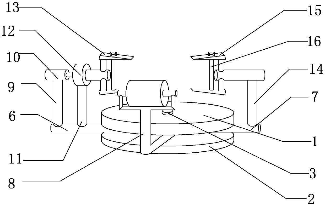
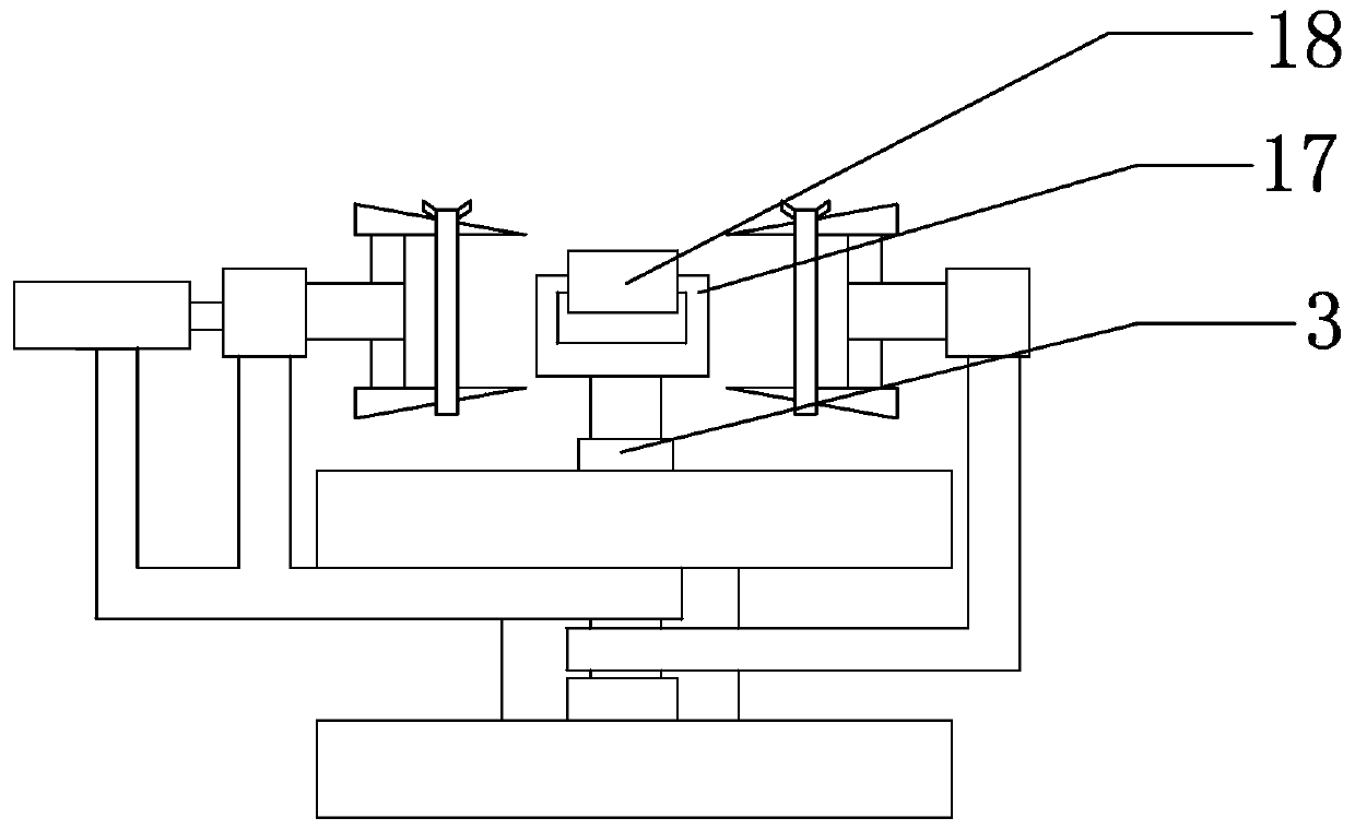
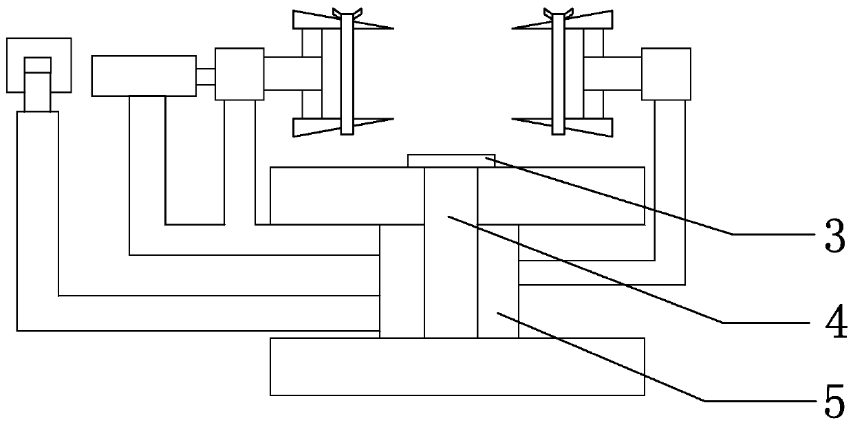
[0024] see Figure 1-3 , in this embodiment: a multi-angle adhesive tape winding and positioning device, including an upper cover 1, the lower volume of the upper cover 1 is provided with a lower cover 2, the upper end of the upper cover 1 is connected with a fixed knob 3, and the fixed knob 3 The lower end of the rotary screw 4 is connected with a rotary screw 4, the outer surface of the rotary screw 4 is surrounded by a screw protective shell 5, the outer surface of the rotary screw 4 is connected with the first connecting rod 6 near the upper cover 1, and the outer surface of the rotary screw 4 is close to The lower end of the first connecting rod 6 is connected with the second connecting rod 7, the outer surface of the rotary screw 4 is connected with the third connecting rod 8 near the lower end of the second connecting rod 7, and the upper end of the first connecting rod 6 is connected with the first supporting rod 9. A motor 10 is connected to the upper end of the first...
PUM
 Abstract
Description
Claims
Application Information