Semi-automatic lifting device

A lifting device, semi-automatic technology, applied in the direction of lifting device, lifting frame, food science, etc., can solve the problems of high production cost of driving equipment, increased operating cost, large energy consumption, etc., and achieves simple structure, easy release, and low failure rate Effect

Active Publication Date: 2020-04-10
杭州承凰科技有限公司
View PDF7 Cites 1 Cited by
  • Summary
  • Abstract
  • Description
  • Claims
  • Application Information

AI Technical Summary

Problems solved by technology

[0004] The above-mentioned lifting device is driven by a hydraulic cylinder. The driving equipment not only has high production costs, but also requires continuous power supply during use, which consumes a lot of energy and increases operating costs.

Method used


Image

  • Semi-automatic lifting device
  • Semi-automatic lifting device
  • Semi-automatic lifting device

Examples


Embodiment Construction

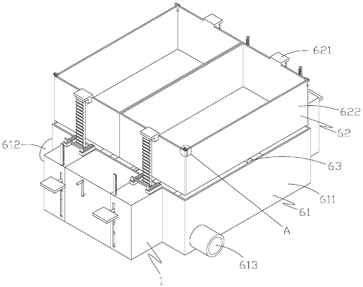
[0029] Such as figure 1 As shown, a semi-automatic lifting device includes a housing 1, a first lifting structure, a first driving structure, a first clamping structure, an energy storage structure, a selection switch structure, a second clamping structure, a second lifting structure and a first Two driving structures; wherein the structure of the first lifting structure is the same as that of the second lifting structure, the structure of the first driving structure is the same as that of the second driving structure, the structure of the first clamping structure is the same as that of the second clamping structure, and the above three pairs of structures Relative to the energy storage structure, they are arranged symmetrically in pairs.

[0030] Specifically, the energy storage structure includes a storage cylinder 21, a first insertion cylinder 22, a second insertion cylinder 23, a storage shaft 24 and an energy storage member 25; , a chute 11 is opened in the housing 1, s...


PUM


Abstract

The invention discloses a semi-automatic lifting device. The semi-automatic lifting device comprises a shell, a first lifting structure, a first driving structure, a first clamping structure, an energy storage structure, a selection switch structure, a second clamping structure, a second lifting structure and a second driving structure, wherein the first lifting structure is arranged in the shell,the first driving structure is matched with the first lifting structure, the first clamping structure is matched with the first lifting structure, the energy storage structure is capable of moving back and forth, the selection switch structure is used for driving the energy storage structure to move back and forth, the second clamping structure is matched with the energy storage structure, the second lifting structure is matched with the second clamping structure and the second driving structure is matched with the second lifting structure. Through cooperative arrangement of the lifting structure, the driving structure, the clamping structure, the energy storage structure and the selection switch structure, a user can drive a lifting rod to ascend and descend in a labor-saving manner, additional driving parts are not needed, the structure is simple, the failure rate is low, and the energy-saving and environment-friendly effects are achieved.

Description

technical field [0001] The invention belongs to the technical field of lifting equipment, and in particular relates to a semi-automatic lifting device. Background technique [0002] In modern industrial production, lifting equipment is widely used, such as rail lifts, scissor lifts, etc., basically using various driving parts to drive, such as hydraulic cylinders, pneumatic cylinders, etc. [0003] For example, the glass lifting device disclosed in Chinese patent CN207030428U includes a driving device, a driving plate and a plurality of lifting columns. One end is fixed on the driving plate, and the free end of the lifting column is accommodated in the glass printing table. The driving device is used to drive the driving plate to move close to or away from the glass printing table. When the driving plate moves close to the glass printing table, the free end of the lifting column Pass through the glass printing table and protrude over the top of the glass printing table to l...

Claims


Application Information

Patent Timeline
Patent Type & Authority Applications(China)
IPC IPC(8): B66F7/12B66F7/28B66F3/02
CPCA23L5/20B66F7/12B66F7/28
Inventor 曾炎
Owner 杭州承凰科技有限公司
Why Eureka
Try Eureka