Synchronous tunnel grouting and drainage construction method for controlling ground heaving
A construction method and technology of simultaneous construction, applied in drainage, tunnel, tunnel lining and other directions, can solve the problems of surface uplift, excessive pore water pressure in the formation, and difficulty in draining the formation water, so as to achieve small disturbance of the formation and low construction cost. , the effect of simple and convenient operation
Active Publication Date: 2020-04-10
中铁南方投资集团有限公司 +1
View PDF6 Cites 6 Cited by
- Summary
- Abstract
- Description
- Claims
- Application Information
AI Technical Summary
Problems solved by technology
For this reason, one of the objects of the present invention is to provide a tunnel grouting and drainage synchronous construction method for controlling surface uplift, by setting vertical water-stop curtains to cut off the water source, setting advanced reverse arch water collection, reverse curved At the bottom of the arch, there are four links: p
Method used
View moreImage
Smart ImageViewing Examples
Examples
 PUM
 Abstract
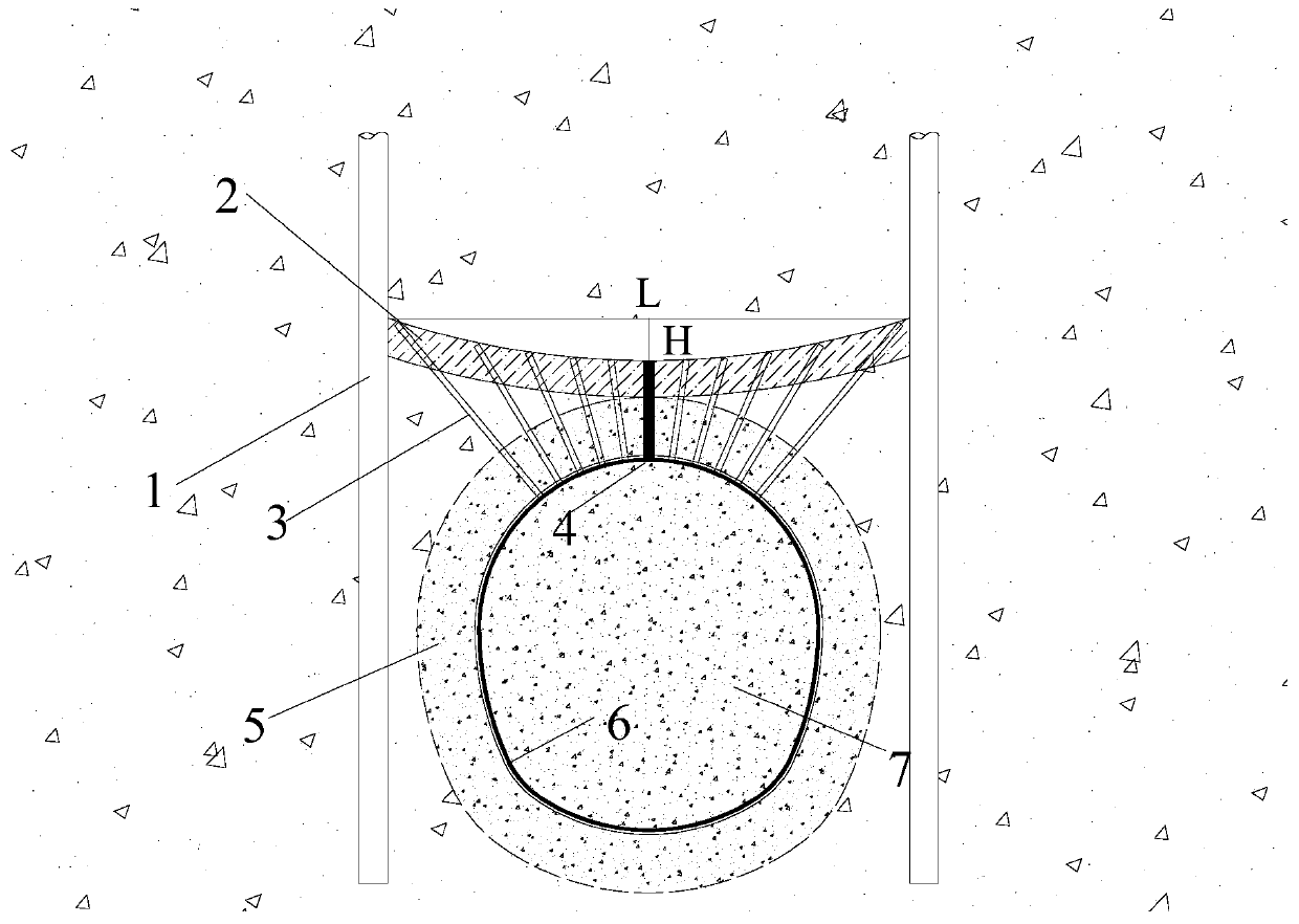
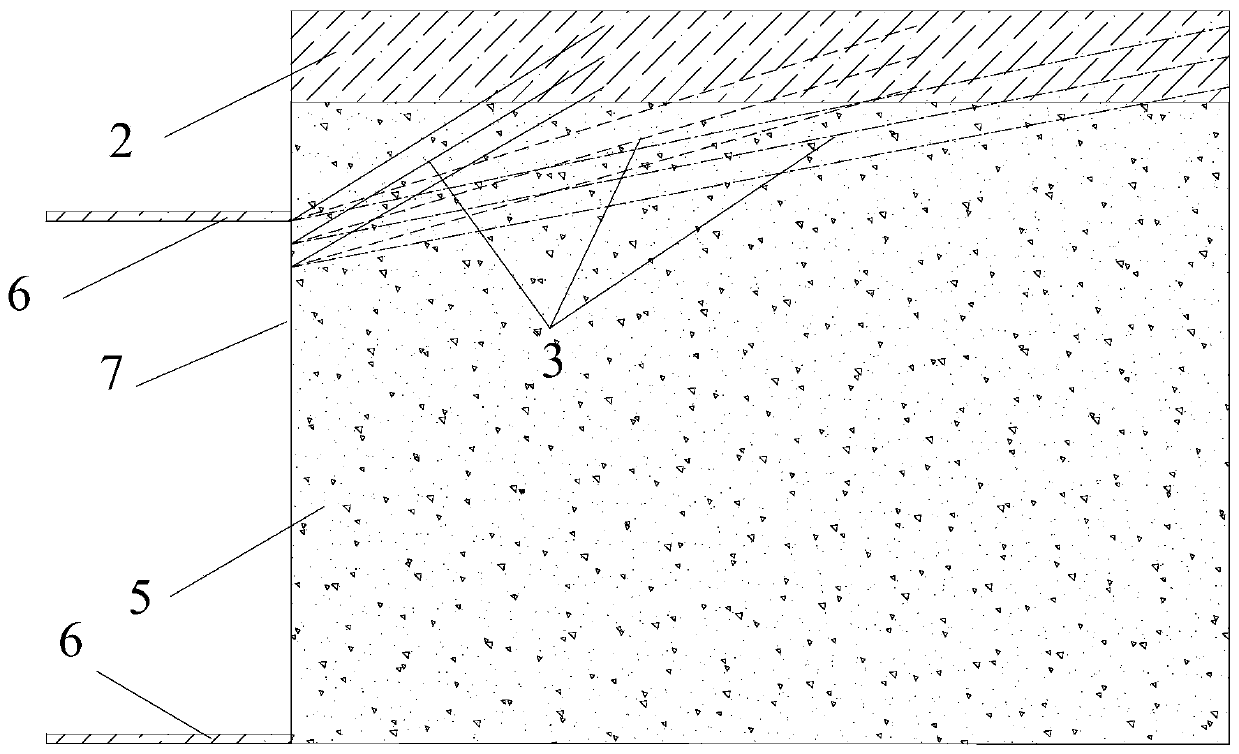
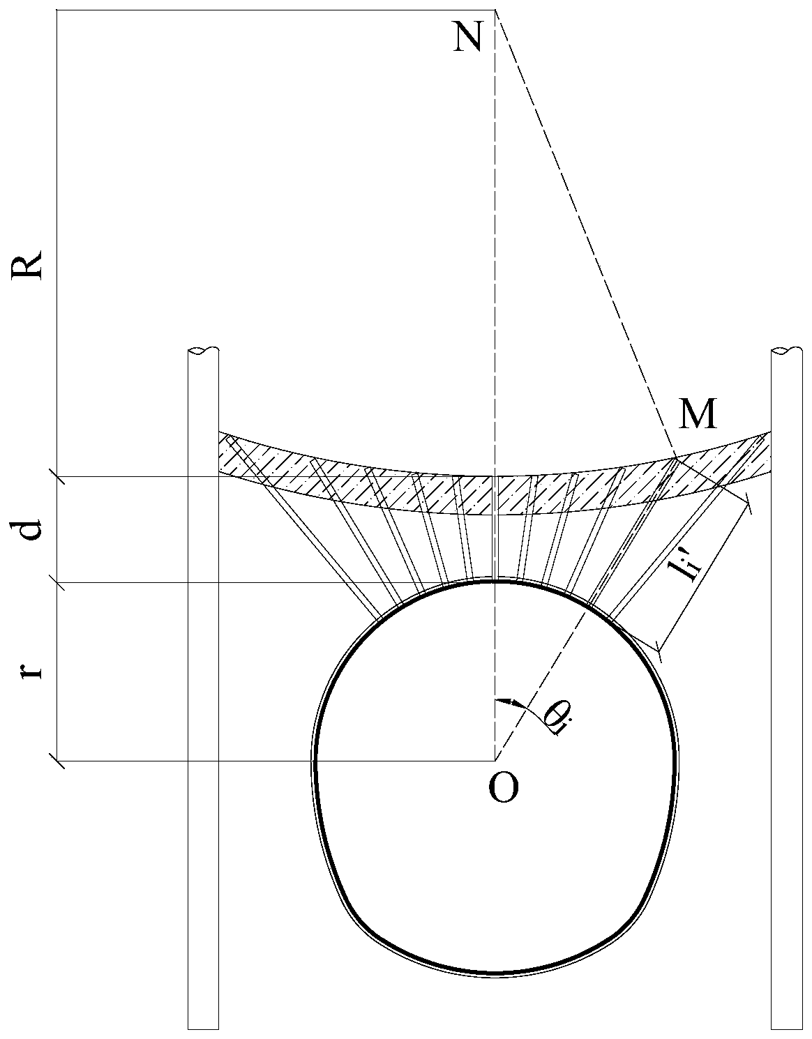
The invention discloses a synchronous tunnel grouting and drainage construction method for controlling ground heaving. The method comprises the following steps that rotary spraying piles are arrangedfrom the ground surface to the two sides of a tunnel to form water stop curtains; after tunnel support is finished, drilling and grouting are carried out above the tunnel face to form an advanced reverse curved arch connecting the water stop curtains on the two sides; after the advanced reverse curved arch is formed, a drainage channel is drilled at the bottom of the advanced reverse curved arch along the tunneling direction, and accumulated water is drained through the drainage channel; and full-section grouting operation is carried out on the tunnel while opening of the drainage channel is guaranteed. The advanced reverse curved arch is in the shape of an arc which is opened towards the ground, water accumulation is easy, and the drainage effect is good after a hole is drilled at the bottom; the originally closed grouting system can be opened by reserving the drainage channel at the bottom of the reverse curved arch, so that drainage work can be synchronously carried out during tunnel advanced pouring construction, excess accumulated water in the stratum is further squeezed and drained by utilizing the lifting effect of grouting, excess pore water pressure caused by grouting construction can be remarkably reduced, and the purpose of preventing excessive ground heaving is achieved.
Description
technical field [0001] The invention belongs to the field of underground and geotechnical engineering, in particular to a tunnel grouting and drainage synchronous construction method for controlling surface uplift. Background technique [0002] Since the beginning of the 21st century, with the rapid economic development and the country's strong support for transportation construction, my country's tunnel and underground engineering construction has achieved unprecedented development, among which the development of urban subway tunnels is particularly rapid. Different from mountain tunnels, the construction of subway tunnels requires less disturbance to the strata and the surrounding environment, and its control standards are also stricter. However, since urban tunnels are often buried at a shallow depth (about 20m), tunnel construction is more likely to have a greater impact on the ground and even superstructures. Therefore, how to achieve construction micro-disturbance is a...
Claims
Login to View More Application Information
Patent Timeline
 IPC IPC(8): E21D11/10E21D11/38E21F16/02
CPCE21D11/10E21D11/38E21F16/02
Inventor 赵勇董宗磊张学民刘继强刘学勤阳军生陈鑫磊冯涵周贤舜贾晓辉喻伟
Owner 中铁南方投资集团有限公司
Features
- R&D
- Intellectual Property
- Life Sciences
- Materials
- Tech Scout
- Unparalleled Data Quality
- Higher Quality Content
- 60% Fewer Hallucinations
Learn More Browse by: Latest US Patents, China's latest patents, Technical Efficacy Thesaurus, Application Domain, Technology Topic, Popular Technical Reports.
© 2025 PatSnap. All rights reserved.Legal|Privacy policy|Modern Slavery Act Transparency Statement|Sitemap|About US| Contact US: help@patsnap.com


