Water stop section for crossing floor layer installation of building drainage pipeline and installation method of water stop section

A technology for building drainage and water-stopping, which is applied in the direction of pipes, pipes/pipe joints/pipes, mechanical equipment, etc. It can solve problems such as affecting the water flow pattern and drainage performance of the drainage riser, increasing the risk of leakage, and affecting the service life. , to achieve good sealing and water-stop function, improve the efficiency of installation and construction, and avoid the effect of corrosion

Pending Publication Date: 2020-06-05
广州观景文化科技有限公司
View PDF0 Cites 6 Cited by
  • Summary
  • Abstract
  • Description
  • Claims
  • Application Information

AI Technical Summary

Problems solved by technology

However, there are still: 1) The pipes are connected to both ends of the pre-embedded pipe respectively, and there are two sealed interfaces, which increases the risk of leakage; 2) The body of the pre-embedded pipe is in contact with sewage and waste water, which will affect its service life due to corrosion; 3) Due to the alignment of the center-adjustable embedded pipe, the upper and lower interfaces may be dislocated, which will affect the water flow pattern and drainage performance in the drainage standpipe; 4) The lower flange of the embedded pipe is connected with a threaded hole t...

Method used


Image

  • Water stop section for crossing floor layer installation of building drainage pipeline and installation method of water stop section
  • Water stop section for crossing floor layer installation of building drainage pipeline and installation method of water stop section
  • Water stop section for crossing floor layer installation of building drainage pipeline and installation method of water stop section

Examples


Embodiment 1

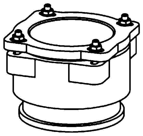
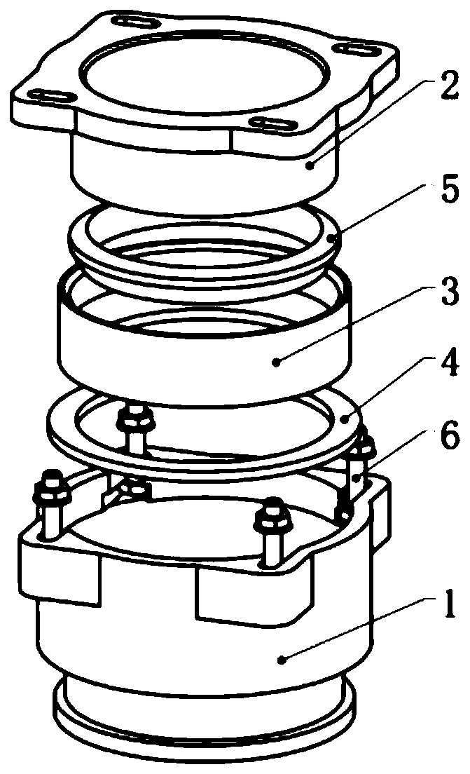
[0054] Such as Figure 1-2 , used for the water-stop section installed by building drainage pipes passing through the floor layer, including the water-stop section body 1, the flange gland 2, the sealing ring sleeve 3, the sealing rubber pad 4, the sealing rubber ring 5 and the fastening bolt 6, the water-stopping The section body 1 and the flange gland 2 are fastened and assembled by fastening bolts 6, and the inner cavity of the waterstop section body 1 is sealed and connected with the sealing ring 3 through the sealing rubber ring 5, and the sealing ring 3 and the flange gland 2 They are sealed and connected by the sealing rubber pad 4 inside the sealing ring sleeve 3 to ensure the tightness of the joint. The water stop section body 1 and the flange gland 2 are set on the drainage riser 7, and the water stop section body 1 is embedded in the floor Layer 8.

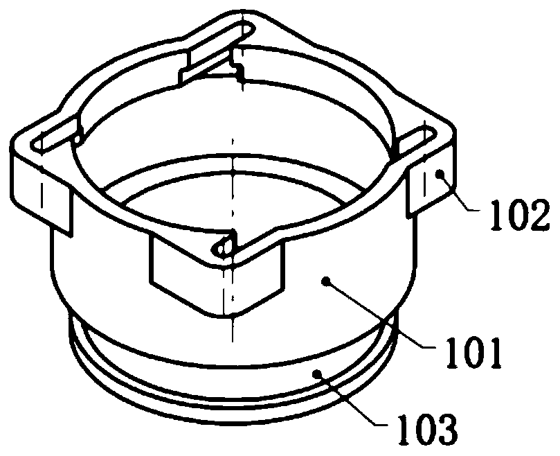
[0055] Water stop festival body 1 (such as Figure 3-4 ) consists of three sections of water-stop pipe body 101 wit...

Embodiment 2

[0069] The water stop section of the present invention is pre-cast in the reinforced concrete floor layer 8. In order to ensure the accuracy of the installation position of the drainage riser 7, before the floor layer 8 is poured, the plane of the water stop section body 1 in the floor layer 8 needs to be fixed. Location. The building drainage riser has a single drainage riser 7 to install, and also has multiple drainage risers 7 to install, all need to be positioned according to the installation dimension requirement of design drawing during installation. as Figure 10 The positioning and installation of the three drainage standpipes 7 is taken as an example, and the positioning and fixing methods are as follows:

[0070] Such as Image 6 According to the size of the installation position on the design drawings, the positioning plate 10 is fixed on the aluminum formwork 9 before pouring with bolts 14 . Set the water stop body 1 on the outer ring of the positioning plate 10...


PUM


Abstract

The invention discloses a water stop section for the crossing floor layer installation of a building drainage pipeline and an installation method of the water stop section. The water stop section includes a water stop section body, a flange gland, a sealing ring sleeve, a sealing rubber pad, a sealing rubber ring and a fastening bolt, the water stop section body and the flange gland are assembledin a fastened mode by the fastening bolt, the inner cavity of the water stop section body is connected with the sealing ring sleeve by the sealing rubber ring in a sealed mode, and the sealing ring sleeve and the flange gland are connected in a sealed mode through the sealing rubber pad inside of the sealing ring sleeve. The risk that water leakage is prone to occurring at openings in the two endsof an embedded connecting pipe or a center-adjustable embedded connecting pipe structure is avoided, a bolt connection fastening method of a T-shaped groove formed in the water stop section body witha cross groove of a flange pressure plate long bolt hole is adopted, when the position of the water stop section poured on a reinforced concrete floor is deviated, the installation position of the pipeline can be conveniently adjusted in any horizontal direction by displacing adjustment to ensure the verticality of the vertical pipe installation, the product structure is simplified, the manufacturing cost is reduced, and the efficiency of installation and construction are improved.

Description

technical field [0001] The invention relates to the technical field of building drainage, in particular to a water stop joint used for installing building drainage pipes through floor floors and an installation method thereof. Background technique [0002] The drainage standpipe of the building drainage system usually needs to pass through the floor layer during the installation process, and the crossing part is generally in the bathroom. In order to prevent the accumulated water on the floor of the toilet from leaking to the toilet on the lower floor through the gap between the outer wall of the pipeline and the structural floor, the following water-stopping measures are often adopted in the design and construction: [0003] 1. Reserve pipe installation holes when pouring in-situ floor slabs. After the pipes are installed, use cement mortar for secondary grouting to close the gap between the pipes and the reserved holes; [0004] 2. The steel casing is embedded in the floo...

Claims


Application Information

Patent Timeline
IPC IPC(8): F16L5/02
CPCF16L5/02
Inventor 师海燕张东海
Owner 广州观景文化科技有限公司
Why Eureka
Try Eureka