
Miniature piezoelectric fan

A piezoelectric fan, miniature technology, applied in the direction of electrical digital data processing, instruments, digital data processing components, etc., can solve the problems of poor heat dissipation effect and affecting application, etc., and achieve the effect of simple structure and good heat dissipation effect

Pending Publication Date: 2020-04-10
KUNSHAN LONGPENG PRECISION ELECTRONICS
View PDF0 Cites 1 Cited by
  • Summary
  • Abstract
  • Description
  • Claims
  • Application Information

AI Technical Summary

Problems solved by technology

[0002] The DC cooling fans used in ultra-thin notebook computers are difficult to reduce due to the size of the blades, and the thickness is more than 3.5mm, while the piezoelectric jet fan can be less than 2.5mm and has attracted attention. In the fields of smart watches and VR headsets, data The processing capacity is getting bigger and bigger, the heat dissipation requirements are also increasing, and the device size is required to be lighter and thinner, but so far, the piezoelectric synthetic jet generators developed so far have the same air inlet and outlet, and the inhaled gas may be The gas that has just been ejected, the gas circulates in a small area, and the gas that is sucked in is often accompanied by heat dissipation, and the heat dissipation effect is poor, which affects its application in specific scenarios. Based on the above defects and shortcomings, it is necessary The technology is improved and a miniature piezoelectric fan is designed

Method used


Image

  • Miniature piezoelectric fan
  • Miniature piezoelectric fan
  • Miniature piezoelectric fan

Examples


Embodiment Construction

[0016] The preferred embodiments of the present invention will be described in detail below in conjunction with the accompanying drawings, so that the advantages and features of the invention can be more easily understood by those skilled in the art, so as to define the protection scope of the present invention more clearly.

[0017] see Figure 1 to Figure 3 , the embodiment of the present invention includes:

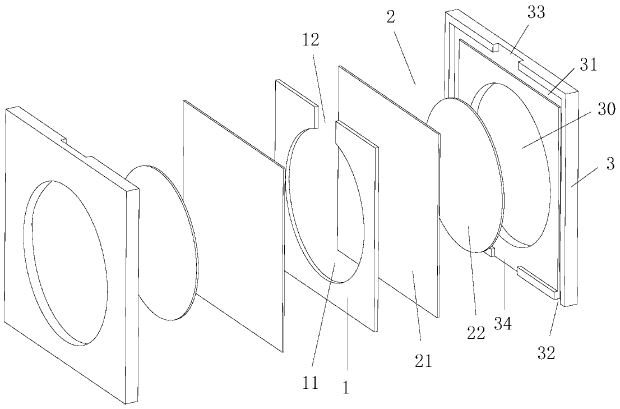
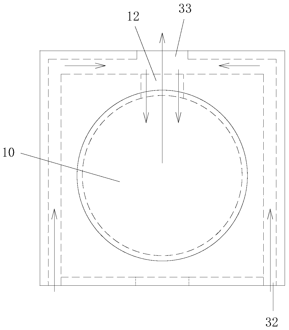
[0018] A miniature piezoelectric fan, which includes an inner support frame 1, a piezoelectric vibrator 2 and an outer support frame 3, piezoelectric vibrators 2 are arranged on both sides of the inner support frame 1, and the inner support frame 1 is provided with There is a circular opening 11, the circular opening 10 and the piezoelectric vibrator 2 on both sides form an adsorption cavity 10, the upper part of the circular opening 11 is provided with a cavity outlet 12, and the piezoelectric vibrator 2 is embedded in the outer support frame 3, The opposite end surf...


PUM


Abstract

The invention discloses a miniature piezoelectric fan. The miniature piezoelectric fan comprises an inner supporting frame, piezoelectric vibrators and outer supporting frames, wherein the piezoelectric vibrators are arranged on the two sides of the inner supporting frame, a circular opening is formed in the inner supporting frame, an adsorption cavity is formed through the circular opening and the piezoelectric vibrators on the two sides, a cavity outlet is formed in the upper portion of the circular opening, the piezoelectric vibrators are embedded in the outer supporting frames, the opposite end faces of the two outer supporting frames are tightly attached, n-shaped grooves are formed in the opposite end faces of the two outer supporting frames, air inlets are formed in the two bottomsof each n-shaped groove, air outlets opposite to the cavity outlet are formed in the tops of the n-shaped grooves, the size of each air outlet is larger than that of the cavity outlet, and wiring holes matched with the piezoelectric vibrators are further formed in the bottoms of the outer supporting frames. By means of the mode, the miniature piezoelectric fan is simple in structure, capable of performing heat dissipation on other equipment, good in heat dissipation effect and different in air inlet and air outlet so as to meet the heat dissipation requirement of portable electronic equipment.

Description

technical field [0001] The invention relates to the technical field of radiators, in particular to a miniature piezoelectric fan. Background technique [0002] The DC cooling fans used in ultra-thin notebook computers are difficult to reduce due to the size of the blades, and the thickness is more than 3.5mm, while the piezoelectric jet fan can be less than 2.5mm and has attracted attention. In the fields of smart watches and VR headsets, data The processing capacity is getting bigger and bigger, the heat dissipation requirements are also increasing, and the device size is required to be lighter and thinner, but so far, the piezoelectric synthetic jet generators developed so far have the same air inlet and outlet, and the inhaled gas may be The gas that has just been ejected, the gas circulates in a small area, and the gas that is sucked in is often accompanied by heat dissipation, and the heat dissipation effect is poor, which affects its application in specific scenarios. ...

Claims


Application Information

Patent Timeline
Patent Type & Authority Applications(China)
IPC IPC(8): F04B45/047F04B39/12G06F1/20
CPCF04B45/047F04B39/123G06F1/20
Inventor 曹明峰
Owner KUNSHAN LONGPENG PRECISION ELECTRONICS
Learn More