
Inclined hole laser cutting method and cutting device

A technology of laser cutting and inclined holes, which is applied in the field of plate processing, can solve problems such as deformation and uneven cooling of plates, and achieve the effect of increasing heat transfer coefficient, reducing recasting layer and heat-affected zone, and improving uniformity

Active Publication Date: 2021-08-06
NANJING INST OF ADVANCED LASER TECH +1
View PDF6 Cites 0 Cited by
  • Summary
  • Abstract
  • Description
  • Claims
  • Application Information

AI Technical Summary

Problems solved by technology

[0004] Technical purpose: Aiming at the problem of uneven cooling and easy deformation of the plate during the cutting process of the existing plate with inclined holes, the present invention discloses a laser cutting method for inclined holes that can be cooled according to the heat field distribution during the plate cutting process and cutting device

Method used


Image

  • Inclined hole laser cutting method and cutting device
  • Inclined hole laser cutting method and cutting device
  • Inclined hole laser cutting method and cutting device

Examples


Embodiment 1

[0052] Taking 1.5mm stainless steel X6Cr17 as an example, the laser direction is 90° perpendicular to the plate. Place the stainless steel plate on the pneumatic fixture, tighten the pneumatic fixture, move the cutting head of the machine tool to the zero position, close the protective door of the machine tool, set the machine parameters, cutting power 3500W, cutting speed 20m / min, focus position -1.5mm, frequency 5000KHz, Gas pressure 1.8MPa. Run the cutting program, the machine tool runs according to the set program trajectory, and the program controls the laser on and off when cutting the path. The cutting direction is perpendicular to the sheet. There is no burr at the laser outlet of the cut sample, and the cutting edge is smooth.

Embodiment 2

[0054] Taking 1.5mm stainless steel X6Cr17 as an example, the laser direction is at an angle of 80° to the plate, that is, the cutting head is inclined at 10°. Place the stainless steel plate on the pneumatic fixture, tighten the pneumatic fixture, move the cutting head of the machine tool to the zero position, close the protective door of the machine tool, set the machine parameters, cutting power 3500W, cutting speed 15m / min, focus position -1.5mm, frequency 5000KHz, Gas pressure 1.8MPa. Run the cutting program, the machine tool runs according to the set program trajectory, and the program controls the laser on and off when cutting the path. The cutting direction is at an angle of 10° to the plate. There is no burr at the laser outlet of the cut sample, and the cutting edge is smooth.

Embodiment 3

[0056] Taking 1.5mm stainless steel X6Cr17 as an example, the laser direction is at an angle of 70° to the plate, that is, the cutting head is inclined at 20°. Place the stainless steel plate on the pneumatic fixture, tighten the pneumatic fixture, move the cutting head of the machine tool to the zero position, close the protective door of the machine tool, set the machine parameters, cutting power 3500W, cutting speed 10m / min, focus position -1.5mm, frequency 5000KHz, Gas pressure 1.8MPa. Run the cutting program, the machine tool runs according to the set program trajectory, and the program controls the laser on and off when cutting the path. The angle between the cutting direction and the plate is 20°. There is no burr at the laser outlet of the cut sample, and the cutting edge is smooth.


PUM


Abstract

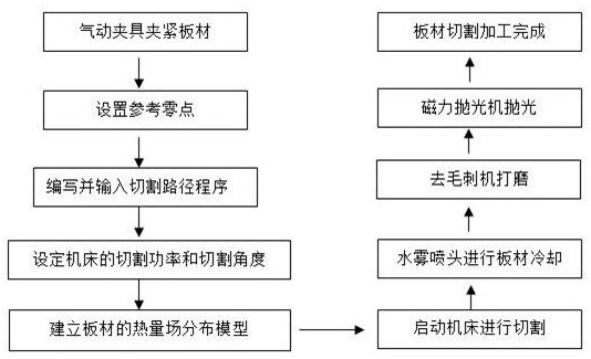
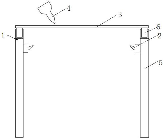
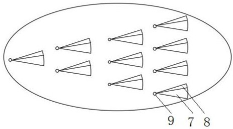
The invention discloses an inclined hole laser cutting method and cutting device. Firstly, a plate is placed on a machining tool to be clamped; then a reference zero point of laser cutting is set, a cutting path program is written according to an inclined hole to be machined, and the cutting path program is input to the machining tool; according to the thickness of the plate, the cutting power and the cutting angle of the machining tool are set, and heat field distribution of the plate in the cutting process is established through simulation software; and finally, the machining tool is started for cutting, nitrogen is used for blowing away slag during cutting, a water mist spray head is arranged below the plate, water mist is sprayed out to cool the plate according to heat field distribution, and final cutting is completed. The water mist spray head is controlled by a plate heat field to correspondingly cool the plate, cooling uniformity is improved, deformation of the plate is avoided, compared with a traditional machining mode, loss is less, machining speed is high, efficiency is higher, control is accurate, and ideal inclined holes can be obtained in a laser cutting mode according to materials of different plate thicknesses and different materials.

Description

technical field [0001] The invention relates to the technical field of plate processing, in particular to a laser cutting method and a cutting device for inclined holes. Background technique [0002] The traditional method of processing inclined holes in sheet metal is to use mechanical drilling machines or milling machines. For this method of contact drilling, it is very difficult to drill small holes on inclined surfaces, especially large-angle inclined surfaces, especially for The processing material is a high-strength, high-hardness material, and it is almost impossible to drill holes; therefore, the current mainstream method is to use a laser to drill holes, and the process does not contact the workpiece, so the processed workpiece is clean and pollution-free, so it eliminates It eliminates the residues caused by conventional hot wire perforation and mechanical perforation, and the processing process is clean and pollution-free. [0003] However, in the laser cutting p...

Claims


Application Information

Patent Timeline
Patent Type & Authority Applications(China)
IPC IPC(8): B23K26/02B23K26/382B23K26/146B23K26/12B23K26/16B23P23/04
CPCB23K26/02B23K26/382B23K26/146B23K26/123B23K26/16B23P23/04
Inventor 于一强朱丽许赟张纪辰谢杨牛岑祚宝
Owner NANJING INST OF ADVANCED LASER TECH
Learn More