Small centrifugal fan

A centrifugal fan and centrifugal fan technology, applied in mechanical equipment, machines/engines, liquid fuel engines, etc., can solve the problems of low oxygen supply efficiency and high aerodynamic noise, and achieve reduced aerodynamic noise, good consistency, and oxygen supply efficiency. high effect

Inactive Publication Date: 2020-04-10
北京北机机电工业有限责任公司
View PDF4 Cites 1 Cited by
  • Summary
  • Abstract
  • Description
  • Claims
  • Application Information

AI Technical Summary

Problems solved by technology

Existing centrifugal fans may cause backflow or reverse flow of air in the fan, low oxygen supply efficiency and large aerodynamic noise

Method used


Image

  • Small centrifugal fan
  • Small centrifugal fan
  • Small centrifugal fan

Examples


Embodiment Construction

[0018] The present invention will be described in detail below with reference to the accompanying drawings and examples.

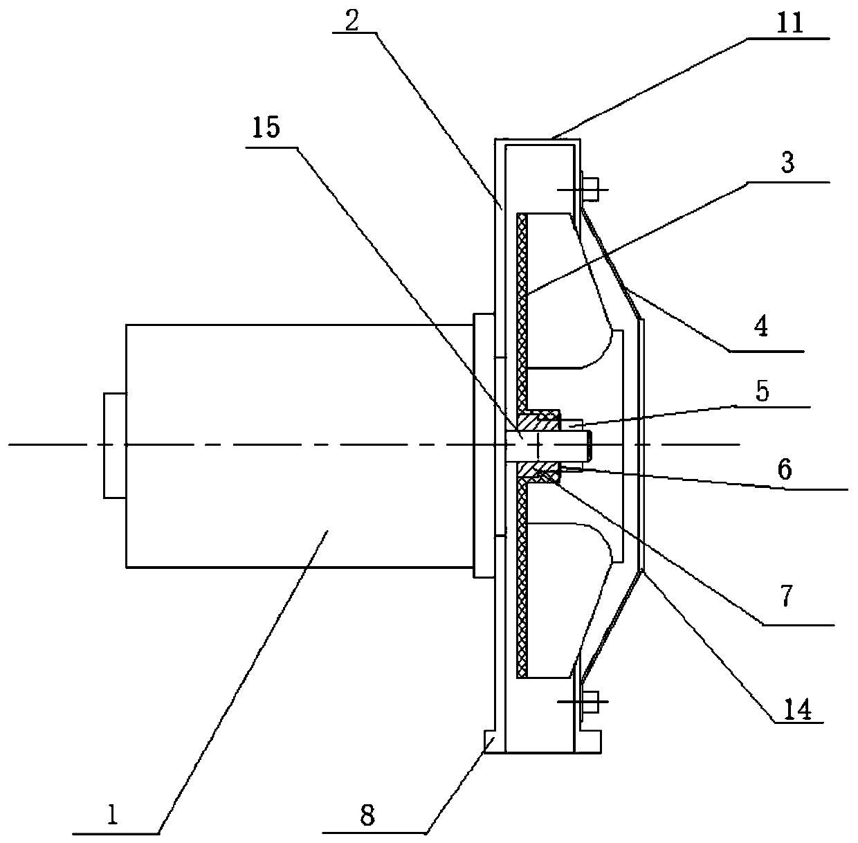
[0019] This embodiment provides a small centrifugal fan, including a motor 1, a volute 2 and a centrifugal fan 3, such as figure 1 shown.

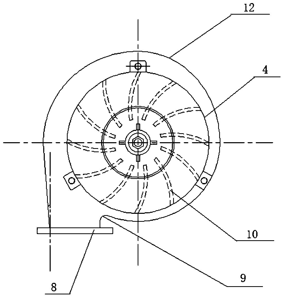
[0020] Such as figure 2 As shown, the volute 2 includes a front cover 4, a rear cover 12, a connecting plate 11, and a flange 8; the front cover 4 and the rear cover 12 are connected by the connecting plate 11 to form a cavity for accommodating the centrifugal fan 3. The flange plate 8 is set at the air outlet of the cavity for docking with other equipment; the angle between the outer wall of the volute 2 and the vertical direction at the place where the outlet part of the volute 2 cooperates with the flange 8 is 5-7 degrees, and the vertical direction The vertical direction is perpendicular to the flange 8, as shown in the figure; the volute tongue 9 of the volute 2 is arc-shaped.

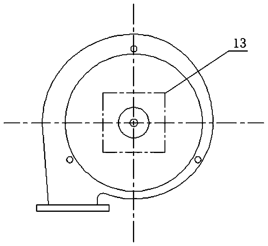
[0021] Such as image 3 As sho...


PUM


Abstract

The invention provides a small centrifugal fan. The small centrifugal fan comprises a motor, a volute and a centrifugal fan body. The volute comprises a front cover plate, a rear cover plate, a connecting plate and a flange plate. The front cover plate and the rear cover plate are connected through the connecting plate to form a cavity for accommodating the centrifugal fan, and the flange plate isarranged at an air outlet of the cavity; the outer contour of the front cover plate and the outer contour of the rear cover plate are formed by involutes with the four vertexes of the square as the circle centers, and the side length of the square and the radius of the base circle of the involutes are determined according to the size of the centrifugal fan. The included angle between the outer wall of the volute at the position where the outlet part of the volute is matched with the flange plate and the vertical direction is 5-7 degrees, and the vertical direction is perpendicular to the flange plate; an air outlet is formed in the center of the front cover plate; the motor is located on the outer side of the volute and fixedly connected with the rear cover plate of the volute, the centrifugal fan is located in the volute, and a mandrel of the centrifugal fan is arranged outside a main shaft of the motor in a sleeving mode and is positioned through a pin penetrating through the main shaft in the radial direction. The centrifugal fan is small in size and high in oxygen supply efficiency.

Description

technical field [0001] The invention relates to the technical field of fluid machinery, in particular to a small centrifugal fan. Background technique [0002] The centrifugal fan is a machine that relies on the input mechanical energy to increase the gas pressure and discharge the gas. It is a driven fluid machine. The centrifugal fan is based on the principle of converting kinetic energy into potential energy. It uses a high-speed rotating impeller to accelerate the gas, then decelerates, changes the flow direction, and converts kinetic energy into potential energy (pressure). [0003] Noise and air volume are the two main indicators of centrifugal fans. It is hoped that the noise will be as small as possible while the air volume can reach a maximum value. The existing centrifugal fan may cause backflow or reverse flow of air in the fan, low oxygen supply efficiency and large aerodynamic noise. Contents of the invention [0004] In order to solve the above problems, th...

Claims


Application Information

Patent Timeline
IPC IPC(8): F04D25/06F04D29/42F04D29/66
CPCF04D25/0606F04D29/4226F04D29/667
Inventor 陈红伟付迎春管小彬齐慧茹王淑红
Owner 北京北机机电工业有限责任公司
Why Eureka
Try Eureka