Industrial fan

A fan and industrial technology, applied in the field of industrial fans, can solve the problems of reduced winding pressure, fan exhaust efficiency, air leakage, and fragility

Inactive Publication Date: 2021-04-27
李良生
View PDF0 Cites 1 Cited by
  • Summary
  • Abstract
  • Description
  • Claims
  • Application Information

AI Technical Summary

Problems solved by technology

[0004] In view of the deficiencies in the prior art, the purpose of the present invention is to provide an industrial fan to solve the problem that the defrosting of the industrial fan is the focus of the construction process of large-scale industrial plants, and the ventilation and mechanical shaft protection of the ice storage need to be strengthened. Due to the cold frost air flow from the ice storage, it will continue to stick to the parts of the mechanical joints such as the blade surface, the shaft and the frame, resulting in frost hardening and brittle phenomenon, causing the ice layer to break and tear the blade , so that the exhaust efficiency of the fan leaks and the winding pressure decreases, which leads to the problem of wasteful operation of the blades in the fan

Method used


Image

  • Industrial fan
  • Industrial fan
  • Industrial fan

Examples


Embodiment 1

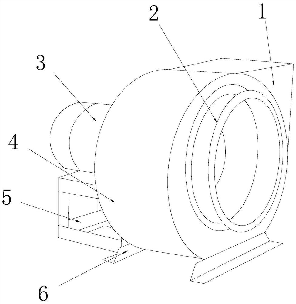
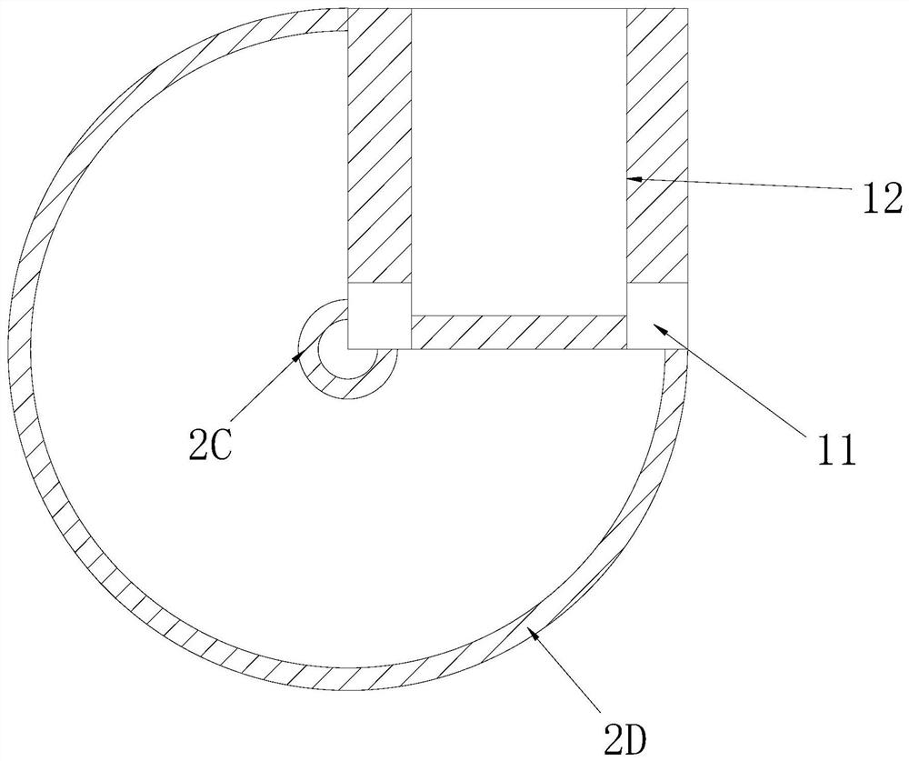
[0035] see Figure 1-Figure 8 , the present invention provides an industrial fan, the structure of which includes: an exhaust duct opening 1, a paddle rack disc groove 2, a shaft motor 3, a fan casing 4, a bracket frame 5, and a gasket 6. The paddle rack disc groove 2 and the fan casing 4 are nested together and the axes are collinear, and the exhaust duct opening 1 is inserted in the rear side of the blade rack disc slot 2 and communicates with each other. The disc groove 2 of the paddle frame is mechanically connected with the shaft motor 3 and the axis is collinear. The shaft motor 3 is installed on the top of the bracket frame 5, and the bracket frame 5 is installed on the fan casing On the left side of 4, two pads 6 are provided and are respectively attached to the left and right lower corners of the fan casing tube 4, and the paddle frame disc groove 2 is provided with a propeller frame rod 2A, a grille groove The baffle plate 2B, the collar body 2C, and the outer frame...

Embodiment 2

[0043] see Figure 1-Figure 8 , the present invention provides a kind of industrial blower fan, other respects are identical with embodiment 1, and difference is:

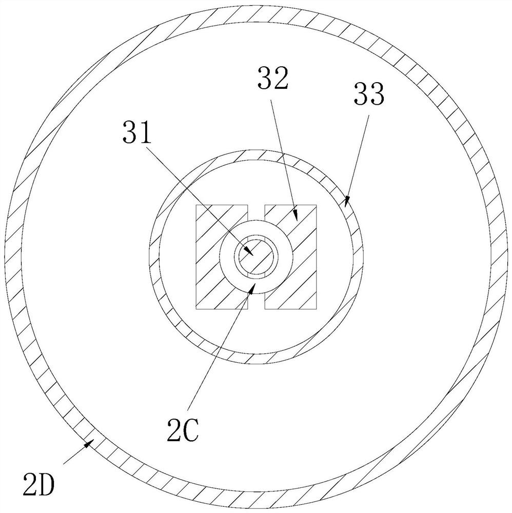
[0044] see image 3 , the shaft motor 3 is composed of a rotor shaft 31, a resistance plate 32, and a motor barrel slot 33, the rotor shaft 31 is electrically connected to the resistance plate 32, and the resistance plate 32 is installed inside the motor barrel slot 33, Through the relay rotation of the rotor shaft 31 linked with the resistance plate 32, the high efficiency of the motor operation is ensured.

[0045] see Image 6 The rotor shaft 31 is composed of a coil arc pressure plate 311, a shaft body 312, and a coil slot 313. The coil arc pressure plate 311 and the shaft body 312 adopt an interference fit, and the shaft body 312 is inserted into the inside of the coil slot 313 And the axis centers are collinear. The coil arc pressure plate 311 is a plate structure with a wide left side and a narrow right s...


PUM


Abstract

The invention discloses an industrial fan. The industrial fan structurally comprises an exhaust pipeline opening, a blade rack disc groove, a shaft driving motor, a fan shell cylinder, a bracket frame base and a filler strip plate. The blade rack disc groove is matched with the shaft driving motor, the framework effect of frost blocking fins is formed on one side of a propeller rack rod through a grating groove baffle, when a fan disc opening is driven by a rotor shaft rod to blow air to conduct airflow, frosted air and an icing layer achieve the effects of sliding block piston movement and damping cushion block friction movement through a sliding strip base block and an ellipsoidal cushion block, the phenomena of rack cooling and freezing degree relieving are formed, it is guaranteed that the oxygen supply efficiency is high in the subsequent continuous cold chain storeroom exhausting and ventilation process, the anti-frosting flexible mechanical treatment efficiency of the inner rack is high, the mechanical sensitivity of linkage of parts in the fan is effectively maintained, and the adaptation degree of cold air and hot air is flexibly adjusted.

Description

technical field [0001] The invention is an industrial blower, which belongs to the field of blowers. Background technique [0002] Industrial fans are ventilation structure tube rack equipment for cold chain warehouse processing in industrial plants. Cooling convection is required to avoid excessive ice agglomeration, ensure long-term preservation of freshness of frozen storage materials, and uniform oxygen supply in the warehouse to improve staff activities. and breathing efficiency, and enhance the working performance of the fan. The shortcomings of the current technology to be optimized are: [0003] The defrosting of industrial fans is the key point of the construction treatment of large industrial plants. The ventilation and mechanical shaft protection of the ice storage need to be strengthened. Since the cold frost airflow of the ice storage is discharged outside, it will continue to stick to the surface of the blade and the shaft. The component area linked with the m...

Claims


Application Information

Patent Timeline
Patent Type & Authority Applications(China)
IPC IPC(8): F04D25/08F04D29/42F04D29/58
CPCF04D25/08F04D29/4206F04D29/4226F04D29/582
Inventor 许美珍
Owner 李良生
Why Eureka
Try Eureka