Conveying device capable of passively adjusting flow

A conveying device and flow rate technology, which is applied in the pipeline system, mechanical equipment, gas/liquid distribution and storage, etc., can solve the problems of too many electrical components, too fast, manual control can not achieve more accurate and timely adjustment, etc.

Active Publication Date: 2020-04-10
XIAN UNVERSITY OF ARTS & SCI
View PDF12 Cites 2 Cited by
  • Summary
  • Abstract
  • Description
  • Claims
  • Application Information

AI Technical Summary

Problems solved by technology

[0004] The disadvantage of the existing technology is that manual control cannot achieve more accurate and timely adjustment, and automatic control has three shortcomings. First, it needs to arrange circuits, which is difficult in some fields, such as temporary irrigation of large-scale farmland, It is difficult to arrange the circuit. Second, there are many electrical components and the cost is high. Third, the overall idea is to monitor the flow or flow rate to control the opening range of the water inlet valve, so as to complete the control of flow rate and flow, but In actual use, the flow rate of the above-mentioned theoretically perfect technical solution still fluctuates, and the instantaneous flow rate is too slow or too fast. The reason is that the pressure of the fluid network is due to the change of flow source pressure, Pulse-like changes often occur due to changes in the number of users. The existing monitoring, feedback, and control modes already have pulses when they are controlled, which has a hysteresis effect and cannot completely eliminate such pulse-like changes.

Method used


Image

  • Conveying device capable of passively adjusting flow
  • Conveying device capable of passively adjusting flow
  • Conveying device capable of passively adjusting flow

Examples


Embodiment Construction

[0033] In order to enable those skilled in the art to better understand the technical solutions of the present invention, the present invention will be further described in detail below in conjunction with the accompanying drawings.

[0034] In each embodiment of the present invention, upstream and downstream are relative to the flow direction of fluid or gas, and the flow direction of fluid or gas is from upstream to downstream, while inside and outside are relative to pipeline 1, such as pipeline 1 inner and outer walls. The intermediate device provided by the present invention is mainly used for the regulation of pulsed liquid flow or air flow, and it can be used alone or in combination with flow rate or flow regulating devices such as automatic regulating valves in the prior art, so as to obtain better technical effects.

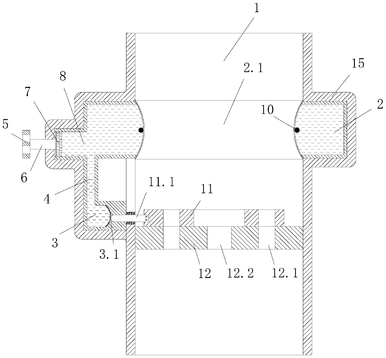
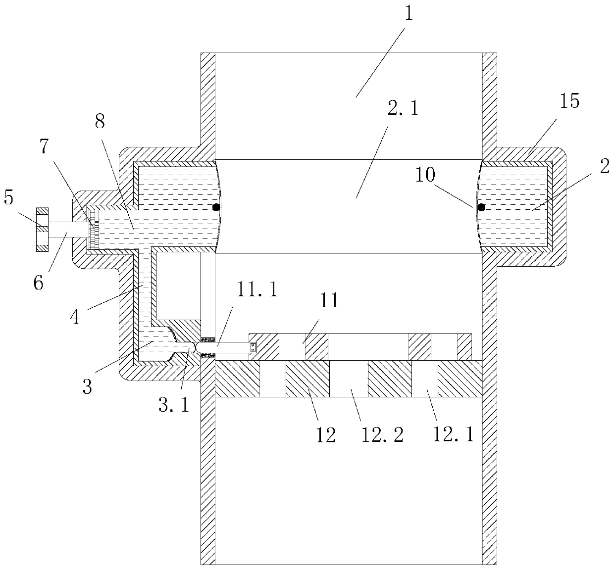
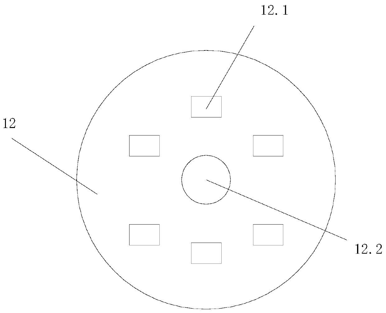
[0035] Such as Figure 1-10 As shown, a delivery device for passive flow adjustment provided by the embodiment of the present invention includes a pipe...


PUM


Abstract

The invention discloses a conveying device capable of passively adjusting flow. The conveying device comprises a pipeline, a transmission mechanism and a flow adjusting assembly; an annular opening isformed in the inner wall of the pipeline; the transmission mechanism comprises an annular driving cavity, a driven cavity and a connecting channel communicating the annular driving cavity and the driven cavity, the annular driving cavity, the driven cavity and the connecting channel are filled with a flowing medium, the inner side wall of the annular driving cavity includes an extrusion deformation piece, and an annular opening is sealed; the flow adjusting assembly comprises a moving part and a plugging barrel, the plugging barrel is plugged at the position, located in the downstream of theextrusion deformation piece, in the pipeline, a plurality of circulating holes are formed in the plugging barrel, and the moving part is movably connected to the plugging barrel; and an elastic telescopic part is arranged on the driven cavity, and the extrusion deformation piece drives, through the extruded stroke, the moving piece to shield the circulation hole. According to the conveying device,adjustment of pulse liquid flow or air flow is passively achieved through the transmission mechanism, and the relatively-constant flow speed and flow are obtained.

Description

technical field [0001] The invention relates to fluid and gas delivery technology, in particular to a delivery device for passive flow regulation Background technique [0002] The transportation of liquid or gas through pipelines exists in almost all walks of life. Generally speaking, the process of liquid transportation needs to be controlled to maintain a constant flow rate. The flow rate control in the prior art includes manual control and automatic control. Among them, Manual control, such as manually controlling the opening range of mechanical valves, realizes flow rate control. Automatic control generally includes sensors, control modules, human-computer interaction modules, and automatic control valves. The data can be used to control the opening range of the automatic control valve, so as to realize the automatic control of flow or flow rate. [0003] In the prior art, for example, the publication number is CN202083670U, the authorized announcement date is November ...

Claims


Application Information

Patent Timeline
Patent Type & Authority Applications(China)
IPC IPC(8): F17D1/08F17D3/01
CPCF17D1/08F17D3/01
Inventor 张运良李浩雷伟军杨森林
Owner XIAN UNVERSITY OF ARTS & SCI
Why Eureka
Try Eureka