Annular support structure and ceramic capacitive pressure sensor using same

A pressure sensor and annular support technology, which is applied in the direction of fluid pressure measurement using capacitance changes, can solve the problems of adverse effects on the accuracy of the capacitive sensor assembly, unpredictability and compensation, and influence on the geometric structure, so as to reduce the accumulation of machining errors and reduce the The effect of gas residue and stability improvement

Active Publication Date: 2020-04-10
INST OF MICROELECTRONICS CHINESE ACAD OF SCI +1
View PDF9 Cites 1 Cited by
  • Summary
  • Abstract
  • Description
  • Claims
  • Application Information

AI Technical Summary

Problems solved by technology

These stick-slip motions affect geometry and can adversely affect the accuracy of capacitive sensor assemblies, are less repeatable, and cannot be predicted and compensated for

Method used


Image

  • Annular support structure and ceramic capacitive pressure sensor using same
  • Annular support structure and ceramic capacitive pressure sensor using same

Examples


Embodiment Construction

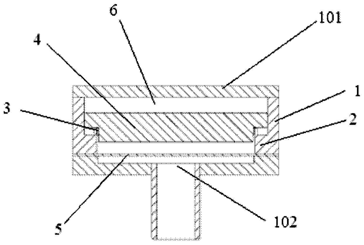
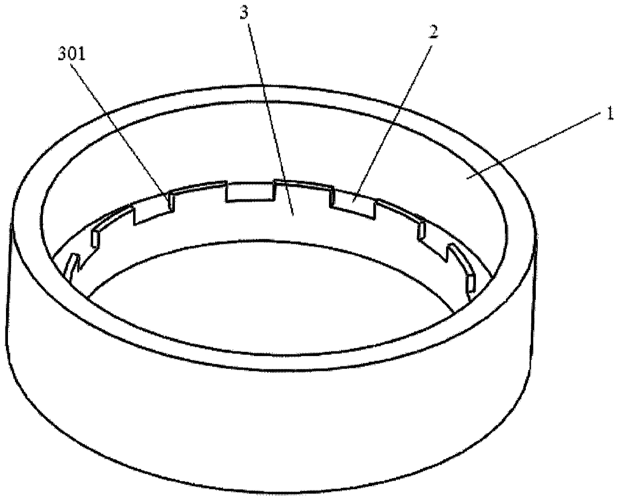
[0020] In view of the prior art, the difference in thermal expansion coefficient between the metal diaphragm and the ceramic fixed electrode causes mechanical hysteresis, thereby affecting the distance d between the metal diaphragm and the ceramic fixed electrode.

[0021] The invention aims to solve the error accumulation caused by the superimposition of one or more components for the distance d between the metal diaphragm and the ceramic fixed electrode. The invention provides an annular support structure for ceramic electrodes of a capacitive pressure sensor. The annular support structure is directly processed and formed on the shell part at one time, and directly supports the ceramic fixed electrode.

[0022] In order to make the object, technical solution and advantages of the present invention clearer, the present invention will be further described in detail below in conjunction with specific embodiments and with reference to the accompanying drawings.

[0023] figure...


PUM

PropertyMeasurementUnit
Wall thicknessaaaaaaaaaa

Abstract

The invention relates to an annular support structure and a ceramic capacitive pressure sensor using the same. The annular support structure comprises a shell; an annular convex part convexly arrangedalong the inner circumferential wall of the shell; a supporting part which extends upwards along the outer edge of the annular convex part, and a plurality of air guide notches formed in the supporting part. On the premise of reducing machining error accumulation, the number and the contact area of spare and accessory parts can be reduced, mechanical hysteresis between the spare and accessory parts caused by temperature drift and other reasons is prevented, and therefore the measurement precision is improved.

Description

technical field [0001] The invention relates to the technical field of sensor electrodes, in particular to an annular support structure and a ceramic capacitive pressure sensor using the same. Background technique [0002] The common structure of a capacitive pressure sensor is to use a metal conductive diaphragm as one of the electrodes of the capacitor, which forms a capacitor with the conductive coating on the ceramic substrate. When the pressure on both sides of the metal diaphragm changes, a pressure difference is generated, causing the metal diaphragm to deform, thereby changing the distance between the metal diaphragm and the conductive layer on the ceramic substrate, and changing the capacitance value. The measurement of the pressure in the measured space is realized by measuring the capacitance value. [0003] In a common structure, the distance between the metal diaphragm and the ceramic electrode is determined by the thickness of one or more gaskets. The control...

Claims


Application Information

Patent Timeline
IPC IPC(8): G01L9/12
CPCG01L9/12
Inventor 林琳李超波郑旭张心强郜晨希王迪刘瑞琪靳毅陈林远雁
Owner INST OF MICROELECTRONICS CHINESE ACAD OF SCI
Why Eureka
Try Eureka