Ring support structure and ceramic capacitive pressure sensor using it

A pressure sensor and ring support technology, which is applied in the direction of fluid pressure measurement using capacitance changes, can solve the problems of adverse effects on the accuracy of the capacitance sensor assembly, cannot be predicted and compensated, and affect the geometric structure, so as to reduce the accumulation of processing errors and reduce Effect of gas residue and stability improvement

Active Publication Date: 2022-06-07
INST OF MICROELECTRONICS CHINESE ACAD OF SCI +1
View PDF9 Cites 0 Cited by
  • Summary
  • Abstract
  • Description
  • Claims
  • Application Information

AI Technical Summary

Problems solved by technology

These stick-slip motions affect geometry and can adversely affect the accuracy of capacitive sensor assemblies, are less repeatable, and cannot be predicted and compensated for

Method used


Image

  • Ring support structure and ceramic capacitive pressure sensor using it
  • Ring support structure and ceramic capacitive pressure sensor using it

Examples


Embodiment Construction

[0020] In view of the prior art, the metal diaphragm and the ceramic electrode due to different material components thermal expansion coefficients lead to mechanical hysteresis, thereby affecting the distance d value between the metal diaphragm and the ceramic electrode.

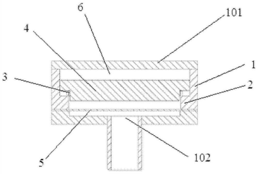
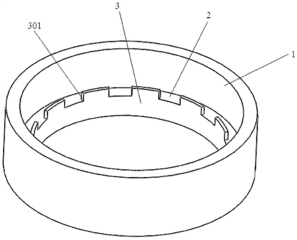
[0021] The present invention solves the error accumulation caused by the superposition of one or more components d between the distance d value of the metal diaphragm and the ceramic electrode. The present invention proposes a capacitive pressure sensor ceramic electrode ring support structure. The ring support structure is directly processed and formed on the shell parts, directly supporting the ceramic fixed electrode.

[0022]To make the object, technical solution and advantages of the present invention more clearly understood, the following in conjunction with specific embodiments, and with reference to the accompanying drawings, the present invention will be further elaborated in detail.

[0023] Figure 1 ...


PUM

PropertyMeasurementUnit
thicknessaaaaaaaaaa
thicknessaaaaaaaaaa

Abstract

An annular support structure and a ceramic capacitive pressure sensor using the same, the annular support structure includes: a housing; an annular protrusion protruding along the inner peripheral wall of the housing; a support part upwards along the outer edge of the annular protrusion Extending, the support part is provided with a plurality of air guide notches. The invention can reduce the number of spare parts and the contact area of ​​the spare parts on the premise of reducing the accumulation of processing errors, prevent mechanical hysteresis between the spare parts caused by temperature drift and the like, thereby improving the measurement accuracy.

Description

Technical field [0001] The present invention relates to the field of sensor electrode technology, in particular to a ring support structure and a ceramic capacitive pressure sensor applied thereto. Background [0002] A common structure for capacitive pressure sensors is the use of a metal conductive diaphragm as one of the capacitor electrodes, and the conductive coating on the ceramic substrate to form a capacitor. When the pressure on both sides of the metal diaphragm changes, the pressure difference is generated, resulting in deformation of the metal diaphragm, thereby changing the distance between the metal diaphragm and the conductive layer on the ceramic substrate and changing the capacitance value. The measurement of the pressure in the measured space is achieved by measuring the capacitance value. [0003] In commonly used structures, the spacing between the metal diaphragm and the ceramic electrode is determined by the thickness of one or more gaskets. The control of th...

Claims


Application Information

Patent Timeline
Patent Type & Authority Patents(China)
IPC IPC(8): G01L9/12
CPCG01L9/12
Inventor 林琳李超波郑旭张心强郜晨希王迪刘瑞琪靳毅陈林远雁
Owner INST OF MICROELECTRONICS CHINESE ACAD OF SCI
Why Eureka
Try Eureka