A Thin Film Capacitive Sensor

A capacitive sensor, thin-film technology, applied in the field of sensors, can solve problems such as temperature drift, different thermal expansion coefficients, and affecting the distance between the metal diaphragm and the ceramic fixed electrode, so as to improve reliability and avoid mechanical hysteresis

Active Publication Date: 2022-02-08
INST OF MICROELECTRONICS CHINESE ACAD OF SCI
View PDF0 Cites 0 Cited by
  • Summary
  • Abstract
  • Description
  • Claims
  • Application Information

AI Technical Summary

Problems solved by technology

[0004] The main purpose of the present invention is to provide a thin-film capacitive sensor to solve the problem that the metal moving electrode and the ceramic fixed electrode are pressed in contact, and the difference in thermal expansion coefficient causes temperature drift, thereby affecting the distance between the metal diaphragm and the ceramic fixed electrode.

Method used


Image

  • A Thin Film Capacitive Sensor
  • A Thin Film Capacitive Sensor
  • A Thin Film Capacitive Sensor

Examples


Embodiment Construction

[0025] In order to make the object, technical solution and advantages of the present invention clearer, the present invention will be further described in detail below in conjunction with specific embodiments and with reference to the accompanying drawings.

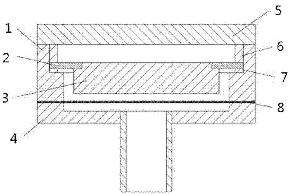
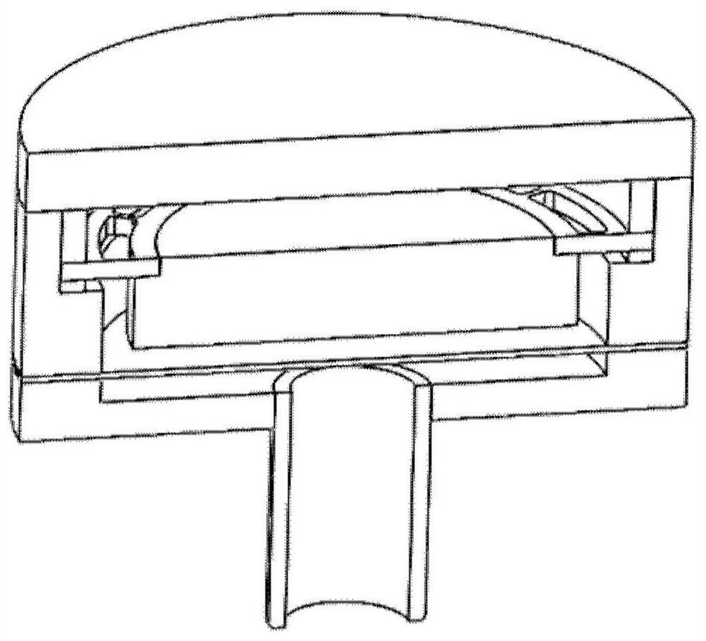
[0026] Such as figure 1 as shown, figure 1 It is a structural schematic diagram of a thin-film capacitive sensor according to an embodiment of the present invention. The thin-film capacitive sensor includes a ceramic fixed electrode 3, a fixed electrode connection ring 2, a casing cover 5, a compression ring 6, an adjustment ring 7, and a diaphragm movable electrode 8 and shell 1, where:

[0027] The ceramic fixed electrode 3 is used as a capacitive plate, and the diaphragm forms a variable capacitor, which is used to detect and output changes in the pressure of the measured environment.

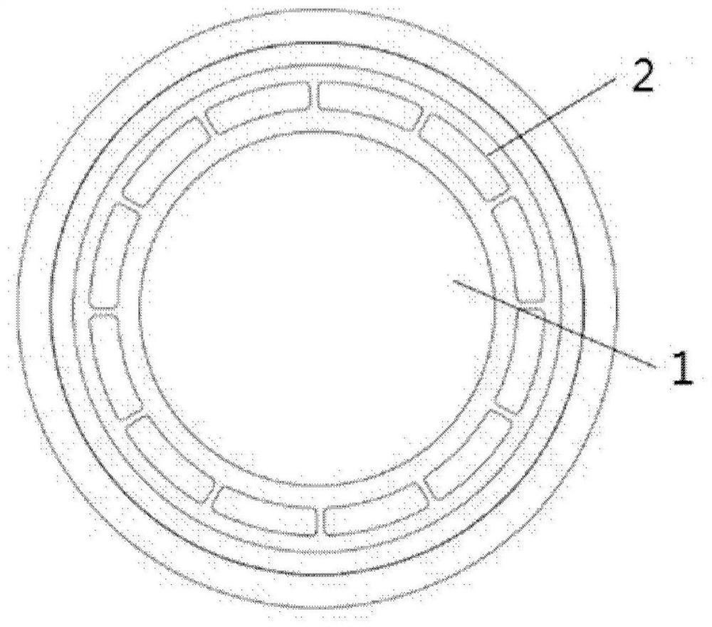
[0028] The fixed electrode connecting ring 2 is used as a medium for connecting the ceramic fixed electrode 3 and the casing 1 .

...


PUM


Abstract

A thin-film capacitive sensor, including a ceramic fixed electrode, a fixed electrode connection ring, a casing, a casing upper cover, a compression ring, an adjustment ring, and a diaphragm movable electrode, wherein: the ceramic fixed electrode is used as a capacitor plate, and the diaphragm movable electrode It forms a variable capacitor, which is used to detect and output the pressure change of the measured environment; the fixed electrode connection ring is used to connect the ceramic fixed electrode and the shell of the thin-film capacitive sensor; the shell is located on the outermost side of the sensor and plays a supporting role; the upper cover of the shell is welded To the shell, it is used to seal the thin film capacitive sensor and compress the fixed electrode connection ring; the compression ring is used to compress the fixed electrode connection ring to prevent the ceramic fixed electrode from slipping; the adjustment ring is used as the diaphragm movable electrode and the ceramic fixed electrode The capacitance distance between them; the moving electrode of the diaphragm acts as a capacitive plate, and forms a variable capacitance with the ceramic fixed electrode. When the external pressure changes, the diaphragm is deformed by force, which causes the distance between it and the ceramic fixed electrode to change, resulting in a change in capacitance .

Description

technical field [0001] The invention relates to the field of sensors, in particular to an anti-sedimentation uniform gas ring. Background technique [0002] Capacitive pressure sensors are usually composed of a moving electrode made of a metal diaphragm and a fixed electrode based on an insulating material such as ceramics. There is a fixed electrode structure between the metal moving electrode and the ceramic fixed electrode, so as to establish capacitance. At present, the commonly used capacitive sensors are fixed on the capacitor shell through the spring contact, but because the thermal expansion coefficient of ceramics is generally 6×10 -6 up to 8×10 -6 m / ℃, while the thermal expansion coefficient of metal is 11×10 -6 to 15×10 -6 m / °C. Therefore, heating or cooling a capacitive sensor assembly can create internal stresses within the assembly, affecting the geometry, especially the distance between the metal diaphragm and the ceramic fixed electrode. Mechanical stre...

Claims


Application Information

Patent Timeline
Patent Type & Authority Patents(China)
IPC IPC(8): G01L1/14G01D5/241
CPCG01L1/142G01D5/2417
Inventor 郜晨希王迪林琳刘瑞琪郑旭远雁李超波
Owner INST OF MICROELECTRONICS CHINESE ACAD OF SCI
Why Eureka
Try Eureka