A bottom hole rotating speed sensor based on centrifugal force

A speed sensor and centrifugal force technology, applied in drilling equipment, drilling measurement, devices using electric/magnetic methods, etc., can solve the problem of not fully adapting to the requirements of bottom-hole power machines, avoid temperature drift problems, and improve reliability. Effect

Active Publication Date: 2018-09-04
CHINA UNIV OF GEOSCIENCES (WUHAN)
View PDF7 Cites 4 Cited by
  • Summary
  • Abstract
  • Description
  • Claims
  • Application Information

AI Technical Summary

Problems solved by technology

Existing methods for measuring the speed of downhole power machines include magnetoelectric speed measurement methods, photoelectric speed measurement methods, flow derivation methods, and pressure pulse methods. Based on the requirements of working in deep wells, it is urgent to develop a speed sensor that can be used specifically for power machines at the bottom of deep holes.

Method used


Image

  • A bottom hole rotating speed sensor based on centrifugal force
  • A bottom hole rotating speed sensor based on centrifugal force
  • A bottom hole rotating speed sensor based on centrifugal force

Examples


Embodiment 1

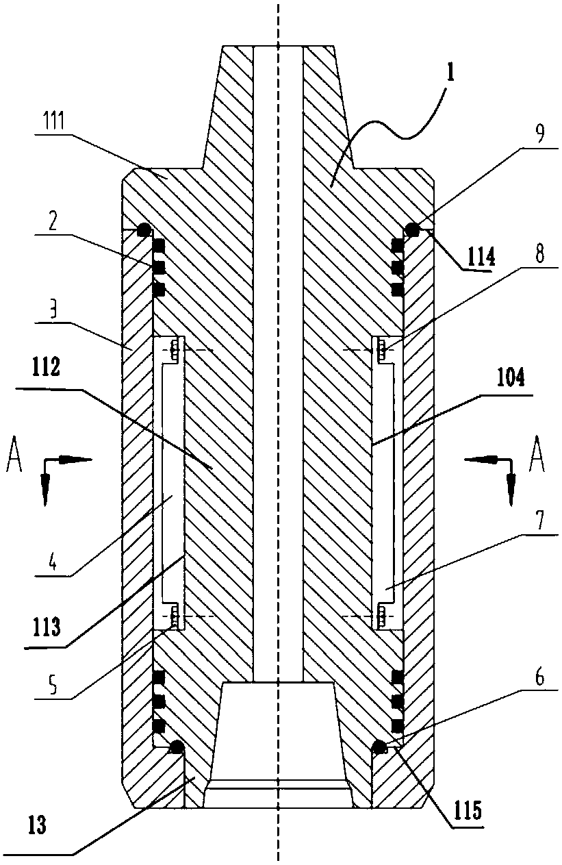
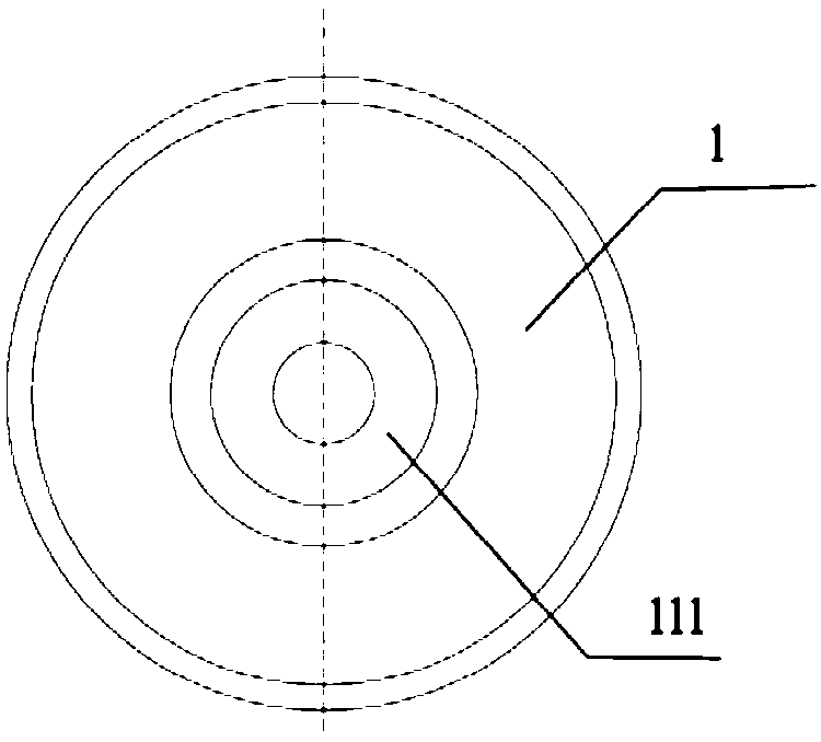
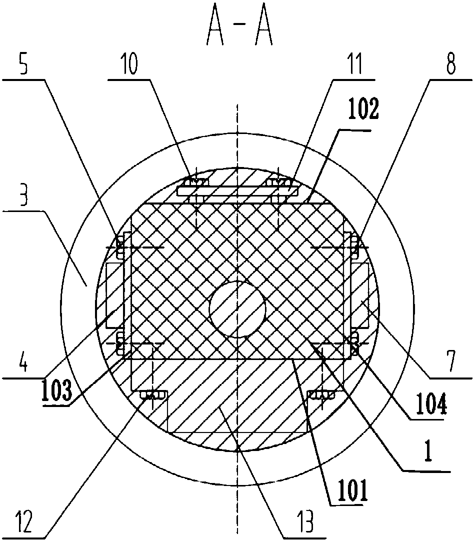
[0038] like Figure 1-3 As shown, the bottom hole speed sensor based on centrifugal force of the present invention includes: a main shaft 1, and a first plane part 101 is formed on the outer peripheral surface of the main shaft 1; a speed detection assembly, which is detachably mounted on the first plane part 101, used to obtain the rotational speed data of the rotating part (such as a power machine at the bottom of a deep hole, etc.); the housing 3, which is threaded outside the main shaft 1, is used to seal the rotational speed detection assembly in the housing 3 and the space between the main shaft 1.

[0039] In this embodiment, the rotational speed sensor can be used to obtain the rotational speed data of the power machine at the bottom of the deep hole. Specifically, the main shaft 1 includes: a head end 111, a middle end 112, and a tail end 113; and the head end 111 and the The middle end 112 is connected to form a first stepped portion 114, and the tail end 113 is con...


PUM


Abstract

The invention discloses a bottom hole rotating speed sensor based on centrifugal force. The sensor includes a main shaft, rotating speed detection components, a shell and a chuck. The rotating speed detection components are removably connected with the main shaft and are used for obtaining the rotating speed data of a rotating part; the main shaft is sleeved by the shell which is used for sealingthe rotating speed detection components between the space between the shell and main shaft; the main shaft is sleeved by the chuck which is abutted with the bottom of the shell and used for avoiding the loosening of the shell. The rotating speed sensor is suitable for the problem of the bottom hole condition environment, and the measuring precision can be greatly improved.

Description

technical field [0001] The invention relates to the fields of oil and gas drilling and geological drilling, in particular to a bottom hole sensor based on centrifugal force. Background technique [0002] Drilling is the process of using drilling rig equipment and rock-breaking tools to break the formation, thereby forming a hole from the surface to the earth at different depths. The traditional drilling process is generally composed of drilling rigs, drill pipes and drill bits. When the drilling depth is deep, the stress state of the drill pipe and the drill bit will become more and more complicated. Under the action of the complex resultant force, the trajectory of the drilling hole will not be kept vertical. At this time, the shape of the trajectory will be complex and changeable. This leads to increased friction between the drill pipe and the inner wall of the borehole during the rotation process, especially for deep drilling, since the length of the drill pipe from the ...

Claims


Application Information

Patent Timeline
Patent Type & Authority Applications(China)
IPC IPC(8): E21B45/00G01P3/44
CPCE21B45/00G01P3/44
Inventor 吴川丁华锋张丹刘雷钧韩磊张心心姚翔宇张雄伟
Owner CHINA UNIV OF GEOSCIENCES (WUHAN)
Why Eureka
Try Eureka