

Thrust rod testing machine
A thrust rod and testing machine technology, which is applied in vehicle testing, mechanical parts testing, machine/structural parts testing, etc., can solve problems affecting the use of thrust rods and large errors in experimental results, so as to achieve realistic and accurate simulation results. Simulate the situation comprehensively and reduce the effect of error
Active Publication Date: 2020-04-10
烟台辰宇汽车部件有限公司
View PDF10 Cites 0 Cited by
- Summary
- Abstract
- Description
- Claims
- Application Information
AI Technical Summary
Problems solved by technology
[0004] The above-mentioned simulation experiment device only simulates and detects the two torsion directions of the thrust rod, and the vehicle will vibrate up and down during actual driving, which will affect the use of the thrust rod. Therefore, the error of the experimental results of the above-mentioned simulation experiment device is relatively large
Method used
View moreImage
Smart ImageViewing Examples

Examples
Embodiment
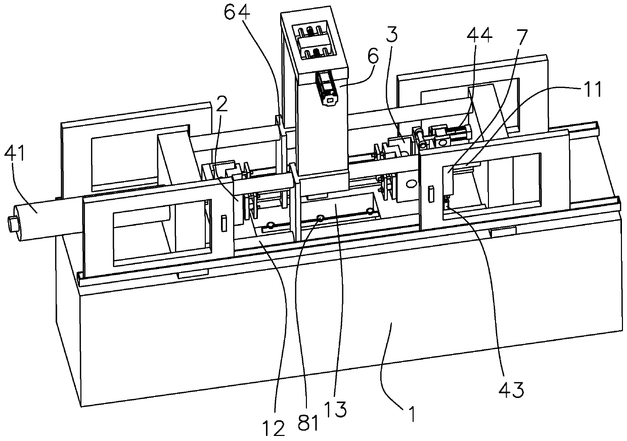
[0038] A thrust rod testing machine such as figure 1 As shown in the figure, it includes a body 1 arranged in the shape of "凵", the two ends of the body 1 are respectively equipped with boom 1 2 and boom 2 3, and the thrust rod is installed between the boom 1 2 and boom 2 3, and the simulation test is carried out .
Login to View More PUM
 Abstract
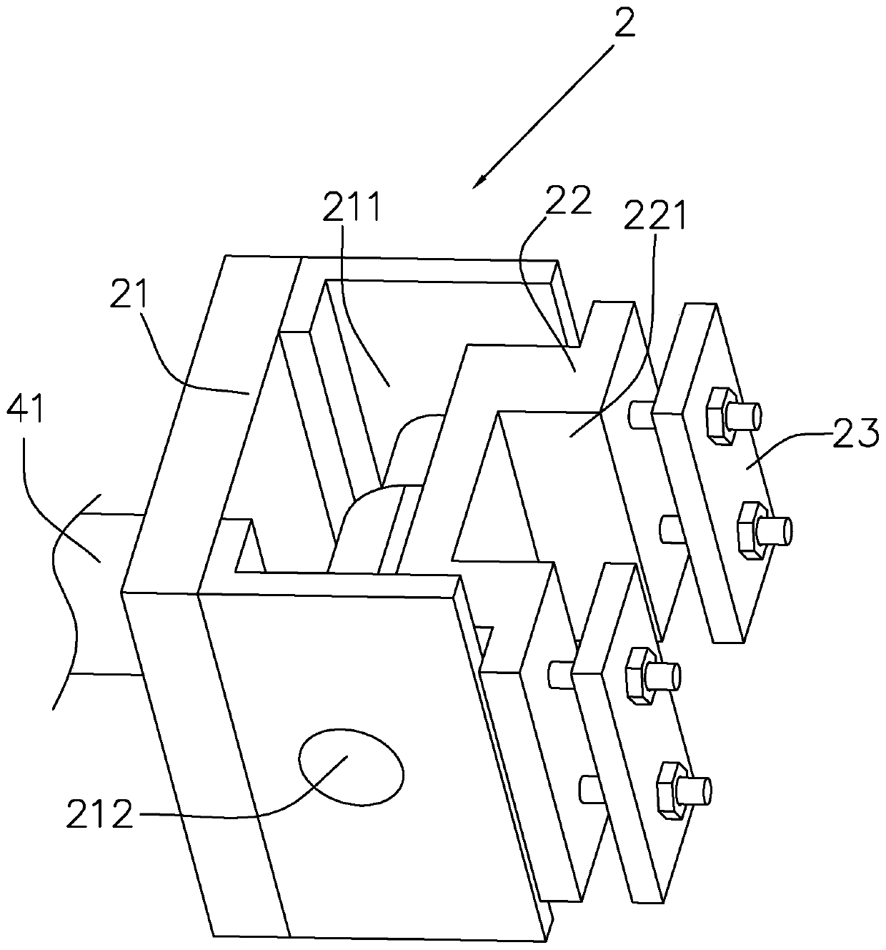
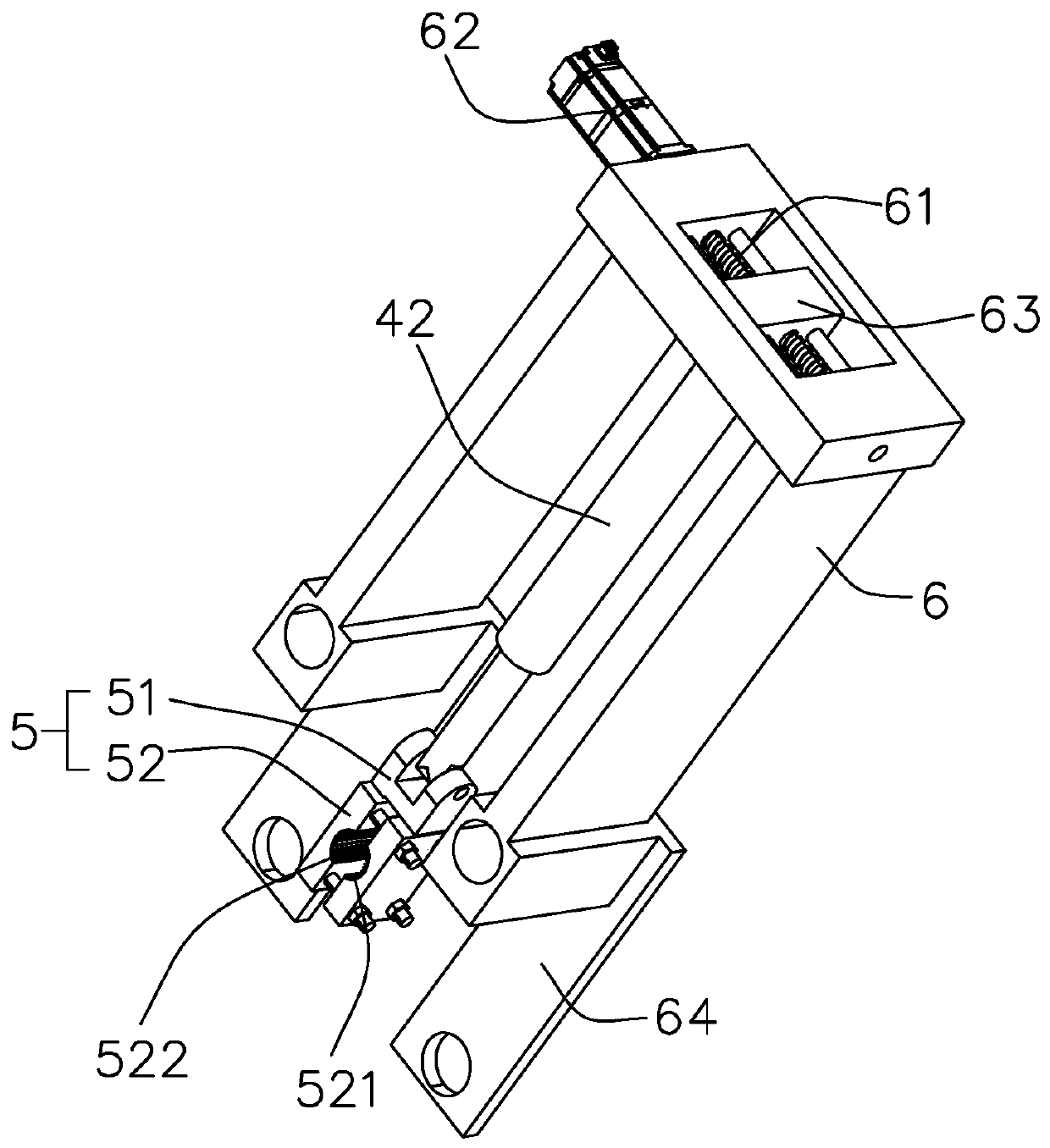
The invention discloses a thrust rod testing machine which comprises a machine body. A first movable arm and a second movable arm are arranged at the two ends of the machine body respectively, a thrust rod is clamped between the first movable arm and the second movable arm. A vertical push cylinder is installed on the machine body, a clamping jaw is hinged to the lower end of the vertical push cylinder, and a clamping gap matching the thrust rod is formed in the clamping jaw. The thrust rod is clamped between the first movable arm and the second movable arm; the thrust rod is clamped on the clamping jaw in the clamping gap, the first movable arm and the second movable arm overturn and swing to conduct force application simulation on the thrust rod, an output shaft of the vertical push cylinder stretches out and draws back, a vertical push-pull force is applied to the thrust rod to simulate the vibration force generated in the vehicle running process. The simulated situation conforms tothe actual running condition, and errors of experiment simulation results are reduced.
Description
technical field [0001] The invention relates to thrust rod testing equipment, in particular to a thrust rod testing machine. Background technique [0002] Thrust rods are important components for heavy trucks and buses to connect the frame and axles and transmit longitudinal and lateral loads. The thrust rod is mainly composed of a head, a shaft and an elastic ball pin, and the two ends are connected together by a steel pipe through hot riveting, and have sufficient connection strength. In order to detect the service life and usage status of the thrust rod, an experimental device is usually required to conduct a simulation experiment on the thrust rod to detect the force and service life of the thrust rod. [0003] The Chinese patent whose notification number is CN2773652Y discloses a kind of vehicle thrust rod simulation experiment device, comprises frame body, has hydraulic drive device and control device on the frame body, and it has a power swing arm and a passive swing...
Claims
Login to View More Application Information
Patent Timeline
 Patent Type & AuthorityApplications(China)
IPC IPC(8): G01M17/007G01M13/00
CPCG01M13/00G01M17/007
Inventor傅运军孙立胜高鹏
Owner烟台辰宇汽车部件有限公司