Magnetic expansion coil winding power mechanism

A braking force and coil technology, which is applied in the manufacture of inductors/transformers/magnets, electrical components, circuits, etc., can solve problems such as loosening and shifting of the skeleton, loosening and slipping of the skeleton of the conductor coil, and low integration of the device, so as to improve the use of Longevity and stability, prevention of skeleton loosening and displacement, stable and reliable fixation

Inactive Publication Date: 2020-04-10
荆门微田智能科技有限公司
View PDF6 Cites 0 Cited by
  • Summary
  • Abstract
  • Description
  • Claims
  • Application Information

AI Technical Summary

Problems solved by technology

[0001] The patent No. 201811178863.2 proposes a transformer coil winding device with a pneumatic expansion and clamping mechanism, which aims to solve the current problem of loosening and shifting of the skeleton due to the lack of effective support of the skeleton during the current transformer coil winding process. At the same time, the problem of inconvenient loading and unloading of the coil skeleton
The fixed end of the frame directly adopts the expansion and tightening drive form of the piston cylinder, the structure is complex, and there are many parts, resulting in a relatively large volume, which cannot meet the needs of small coil production.
Because it uses a pneumatic method to e

Method used


Image

  • Magnetic expansion coil winding power mechanism
  • Magnetic expansion coil winding power mechanism
  • Magnetic expansion coil winding power mechanism

Examples


Embodiment Construction

[0020] The present invention is further described in conjunction with the following examples.

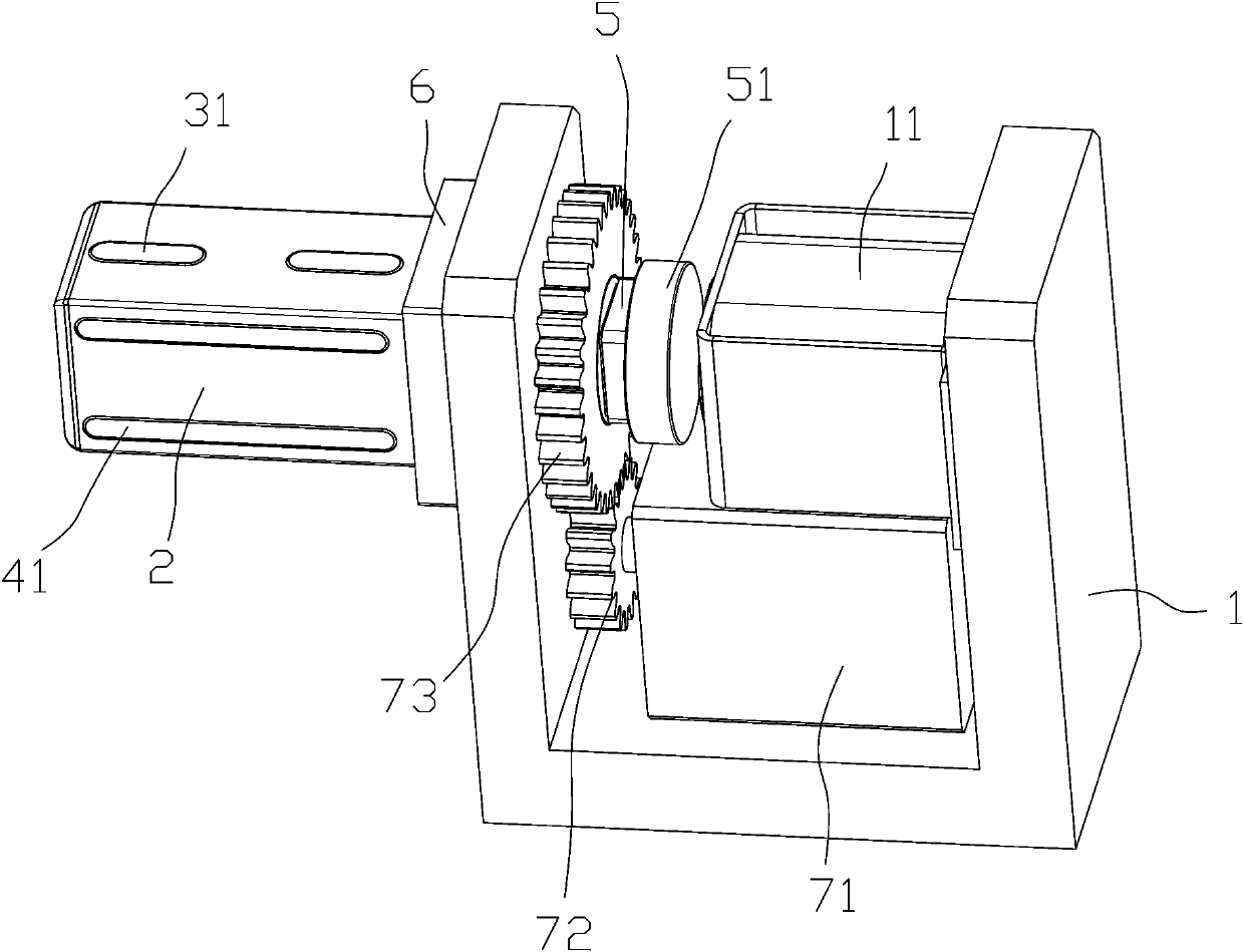
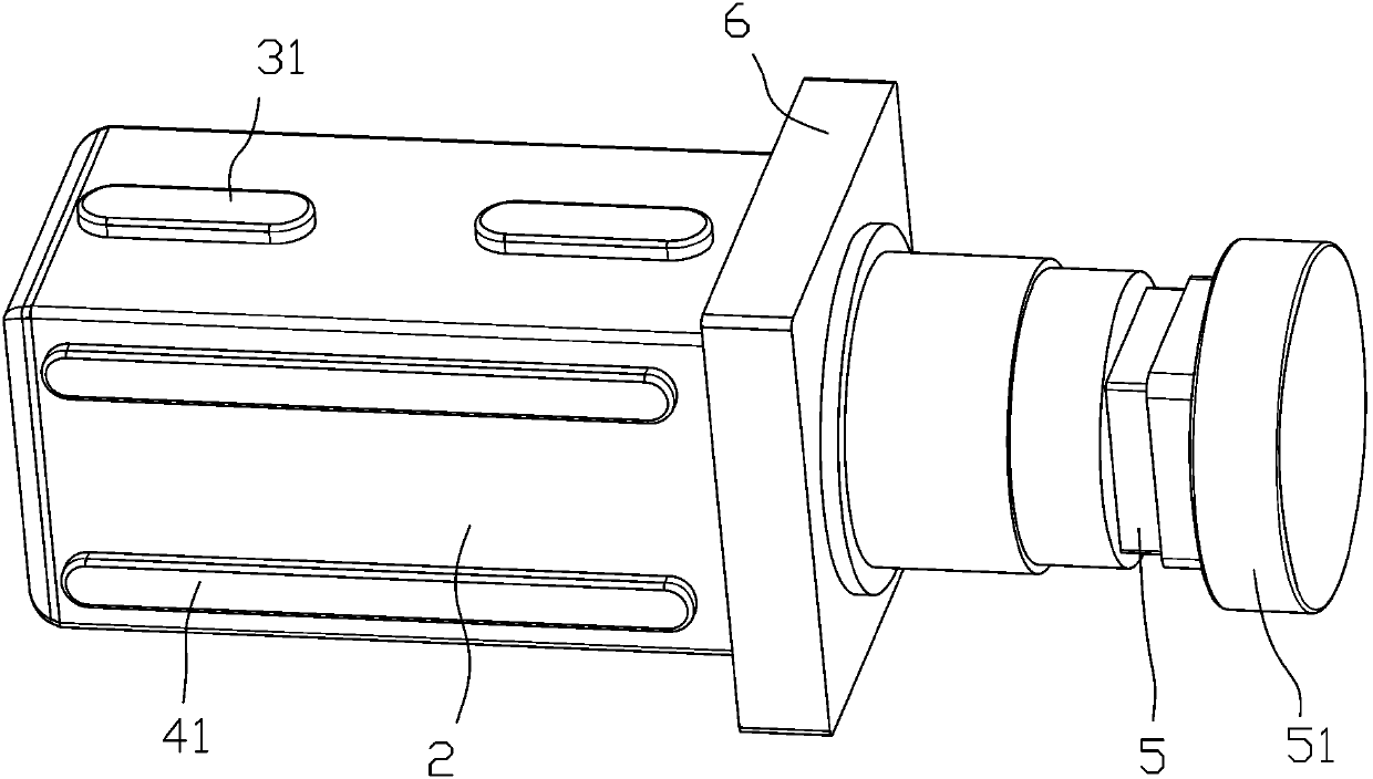
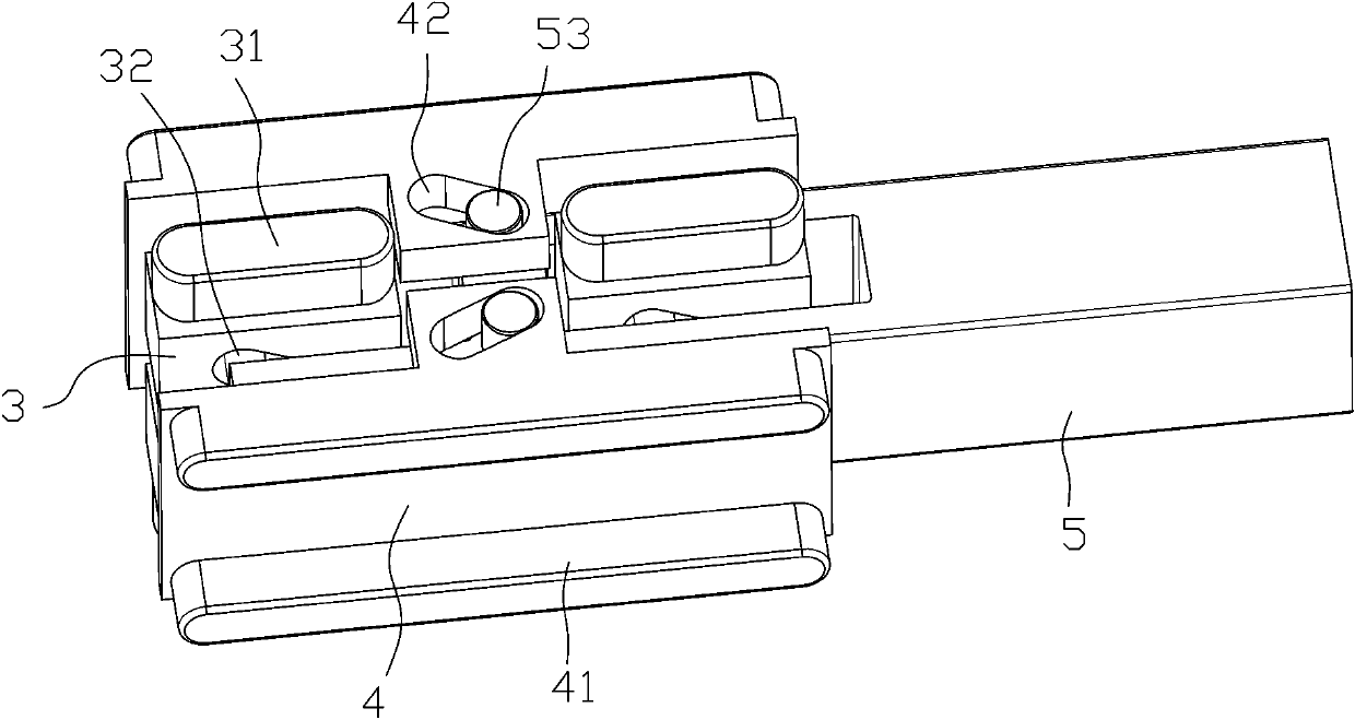
[0021] Depend on Figure 1 to Figure 4 It can be seen that a magnetic expansion coil winding braking power mechanism described in this embodiment includes a bracket 1, an electromagnet 11 fixed on the bracket 1, a rotating expansion shaft 2 located on the bracket 1, and a driving shaft for driving the expansion shaft. 2 rotating rotating components;

[0022] The first expansion plate 3 is movable on both sides of the upper and lower sides of the expansion shaft 2; the second expansion plate 4 is movable on the left and right sides of the expansion shaft 2; the first expansion plate 3 And the second expansion plate 4 moves along the radial direction of the expansion shaft 2;

[0023] The expansion shaft 2 is movable and provided with an expansion block 5 for driving the first expansion plate 3 and the second expansion plate 4 to move; the expansion block 5 moves along the axial dir...


PUM


Abstract

The invention relates to the technical field of transformers, in particular to a magnetic expansion coil winding power mechanism which comprises a support, an electromagnet, an expansion shaft and a rotating assembly. The expansion shaft is provided with a first expansion plate and a second expansion plate; and the expansion shaft is movably provided with an expansion block used for driving the first expansion plate and the second expansion plate to move. The expansion block moves along the axial direction of the expansion shaft; the end, close to the electromagnet, of the expansion block extends out of the expansion shaft and then is connected with a permanent magnet. The coil framework is fixed through the expansion shaft, fixing is stable and reliable, and the situation that the productquality is reduced due to the fact that the framework loosens and shifts in the coil winding process is prevented; the expansion torque is transmitted in a non-contact mode through an electromagneticfield, the service life is greatly prolonged, and the stability is greatly improved; and the magnetic field intensity output by the electromagnet can be adjusted by adjusting the magnitude of the current, so that the expansion force is adjusted to meet the fastening force requirements during winding of coils with different wire diameters, and the applicability to production of different productsis improved.

Description

Background technique [0001] The patent No. 201811178863.2 proposes a transformer coil winding device with a pneumatic expansion and clamping mechanism, which aims to solve the current problem of loosening and shifting of the skeleton due to the lack of effective support of the skeleton during the current transformer coil winding process. At the same time, it is inconvenient to load and unload the coil frame. The fixed end of the frame directly adopts the expansion and tightening drive form of the piston cylinder, the structure is complex, and there are many parts, resulting in a relatively large volume, which cannot meet the needs of small coil production. Because it uses a pneumatic method to expand and tighten the coil frame, it is necessary to use a rotary air supply device to continuously supply air to the high-speed rotating frame expansion mechanism. Due to the relatively large volume of the rotary air supply device, the integration of the entire device is very low, maki...

Claims


Application Information

Patent Timeline
IPC IPC(8): H01F41/082H01F41/094
CPCH01F41/082H01F41/094
Inventor 高天一
Owner 荆门微田智能科技有限公司
Why Eureka
Try Eureka