Eureka AIR delivers breakthrough ideas for toughest innovation challenges, trusted by R&D personnel around the world.

Flywheel motor mounting tool

A technology for installing tools and flywheel motors, which is used in electromechanical devices, manufacturing motor generators, electrical components, etc., can solve the problems of flywheel motor damage, finger injuries of assemblers, and high suction, and achieves high installation accuracy and meets concentricity. and anti-collision requirements, the effect of easy installation

Inactive Publication Date: 2020-04-10
CHINA NORTH ENGINE INST TIANJIN
View PDF7 Cites 0 Cited by
  • Summary
  • Abstract
  • Description
  • Claims
  • Application Information

AI Technical Summary

Problems solved by technology

[0002] The gap between the stator and the rotor of the flywheel motor is very small (usually about 1mm, after various processing deviations accumulate, it is difficult to ensure that the gap after assembly is within the allowable range of the required value), on the other hand, because the inside of the rotor is equipped with High-strength magnetic steel, in the process of installation and disassembly, has a strong suction force, which is easy to cause the finger injury of the assembler and the damage of the flywheel motor due to collision. This invention is a tool invented for the concentricity and anti-collision requirements in the installation process of the flywheel motor

Method used


Image

  • Flywheel motor mounting tool
  • Flywheel motor mounting tool
  • Flywheel motor mounting tool

Examples


Embodiment Construction

[0022] It should be noted that, in the case of no conflict, the embodiments of the present invention and the features in the embodiments can be combined with each other.

[0023] In describing the present invention, it should be understood that the terms "center", "longitudinal", "transverse", "upper", "lower", "front", "rear", "left", "right", " The orientations or positional relationships indicated by "vertical", "horizontal", "top", "bottom", "inner" and "outer" are based on the orientations or positional relationships shown in the drawings, and are only for the convenience of describing the present invention and Simplified descriptions, rather than indicating or implying that the device or element referred to must have a particular orientation, be constructed and operate in a particular orientation, and thus should not be construed as limiting the invention. In addition, the terms "first", "second", etc. are used for descriptive purposes only, and should not be understood ...


PUM


Abstract

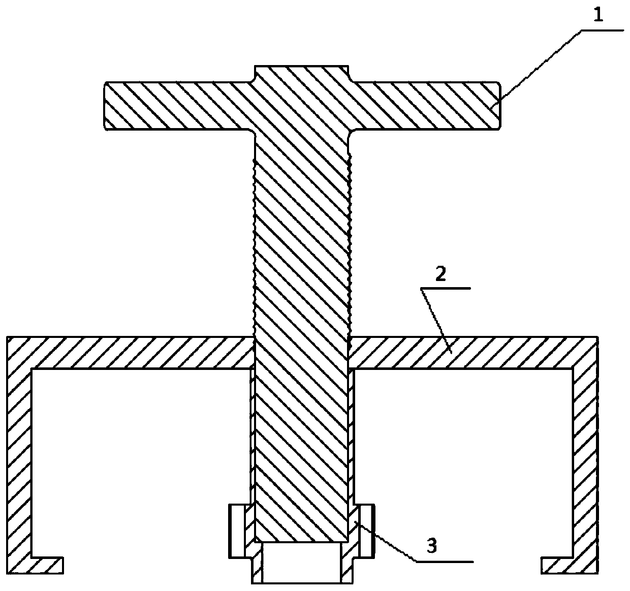
The invention provides a flywheel motor mounting tool, which comprises a rotary rod which comprises a T-shaped structure composed of a vertical rotating column and a rotating handle fixedly connectedwith the rotating column, a rotor frame which comprises a threaded ring and two rotor hooks which are symmetrically arranged left and right, a stator positioning sleeve, wherein the whole stator positioning sleeve is of a cylindrical structure, and the cylindrical structure sequentially comprises a crankshaft positioning section, a stator positioning section and a rotary rod fixing section from bottom to top. According to the invention, the concentricity and anti-collision requirements in the installation process of the flywheel motor are met, the installation is convenient, and the installation precision is high.

Description

technical field [0001] The invention belongs to the technical field of flywheel motors, and in particular relates to a flywheel motor installation tool. Background technique [0002] The gap between the stator and the rotor of the flywheel motor is very small (usually about 1mm, after various processing deviations accumulate, it is difficult to ensure that the gap after assembly is within the allowable range of the required value), on the other hand, because the inside of the rotor is equipped with High-strength magnetic steel, in the process of installation and disassembly, has a strong suction force, which is easy to cause the finger injury of the assembler and the damage of the flywheel motor due to collision. This invention is a tool invented for the concentricity and anti-collision requirements in the installation process of the flywheel motor . Contents of the invention [0003] In view of this, the present invention aims to provide a flywheel motor installation too...

Claims


Application Information

Patent Timeline
Patent Type & Authority Applications(China)
IPC IPC(8): H02K15/00
CPCH02K15/00
Inventor 董江峰孙淑慧徐广辉陈晋兵牛海杰
Owner CHINA NORTH ENGINE INST TIANJIN
Why Eureka
Eureka Blog
Learn More