
Phase adjuster concentricity air inflation adjusting clamp and device

A phase adjuster and adjusting device technology, which is applied to workpiece clamping devices, assembling machines, manufacturing tools, etc., can solve the problem that the adjustment method cannot meet the requirements, and achieve the effects of low cost, strong economic applicability, and improved applicability

Pending Publication Date: 2019-04-09
HAILIDA AUTOMOBILE TECH CO LTD
View PDF9 Cites 0 Cited by
  • Summary
  • Abstract
  • Description
  • Claims
  • Application Information

AI Technical Summary

Problems solved by technology

[0007] However, limited by the processing accuracy of the fixture itself, the concentricity that can be achieved through the fixture is 0.04mm, and the design requirements are usually 0.02-0.09mm. For phase regulators that require concentricity less than 0.04mm, mechanical The fixture adjustment method cannot meet the requirements

Method used


Image

  • Phase adjuster concentricity air inflation adjusting clamp and device
  • Phase adjuster concentricity air inflation adjusting clamp and device
  • Phase adjuster concentricity air inflation adjusting clamp and device

Examples


Embodiment 1

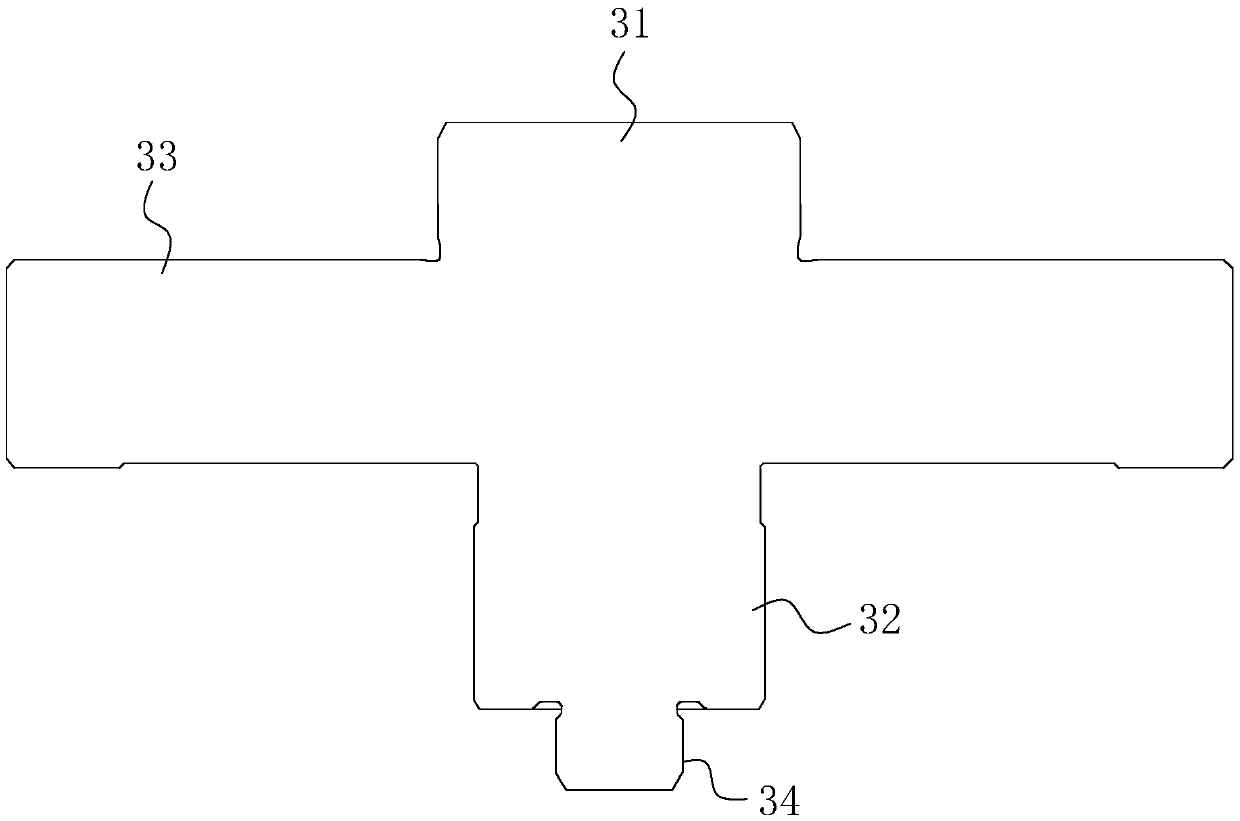
[0034] A phase adjuster concentricity inflatable adjusting fixture, refer to Figure 4 , which includes an adjusting plate 33. In this embodiment, the adjusting plate 33 is disc-shaped; the two ends of the adjusting plate 33 are respectively provided with a first pillar 31 and a second pillar 32, and the end face of the second pillar 32 away from the adjusting plate 33 is provided with a positioning Column 34 ; in this embodiment, the first column 31 , the adjusting plate 33 , the second column 32 and the positioning column 34 are arranged coaxially.

[0035] refer to image 3 , the end face of the first strut 31 is provided with an inflation channel extending to the end face of the second strut 32. In this embodiment, the inflation channel includes a first air channel 35 and a second air channel 36; the first air channel 35 is opened on the end face of the first strut 31 In the middle, it extends inward into the second pillar 32; the second air passage 36 is opened on the en...

Embodiment 2

[0039] A phase adjuster concentricity inflatable adjusting device, refer to Figure 5 , which includes a fixed bottom frame for carrying the clamp in Embodiment 1, the fixed bottom frame includes a fixed bottom plate 41, and the bottom wall of the fixed bottom plate 41 is provided with four fixed bottom columns 42 evenly distributed; the fixed bottom frame is provided with a fixed top frame, The fixed top frame includes a fixed top plate 43, and the bottom wall of the fixed top plate 43 is evenly provided with four fixed top columns 44 connected with the top wall of the fixed bottom plate 41; figure 1 ) on the five bolt holes 12 (refer to figure 1 )Corresponding.

[0040] refer to Image 6 , the adjusting plate 33 is connected with the bottom wall of the fixed bottom plate 41, and the bottom wall of the fixed bottom plate 41 is provided with a positioning slot 412 for inserting the first pillar 31; 411, an inflatable tube connected to an inflatable device is inserted in the...


PUM


Abstract

The invention discloses a phase adjuster concentricity air inflation adjusting clamp and device, and relates to the technical field of phase adjuster assembly. The clamp and the device aim to solve the problem that a traditional clamp is limited by machining precision so that the concentricity cannot completely meet design requirements. According to the technical scheme, the clamp is characterizedby comprising an adjusting plate, a first supporting column and a second supporting column are arranged on the two sides of the adjusting plate correspondingly, the end, far away from the adjusting plate, of the second supporting column is provided with a positioning column, and an air inflation channel extending to the end face of the second supporting column is formed in the end face of the first supporting column. According to the clamp and the device, the effect of improving the concentricity adjusting precision is achieved so that the concentricity of a stator and a rotor can completelymeet the design requirements.

Description

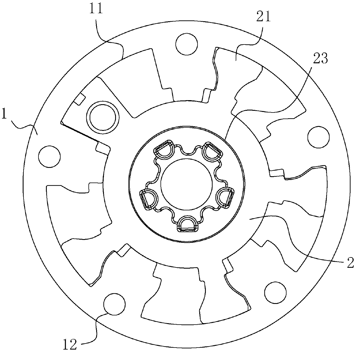
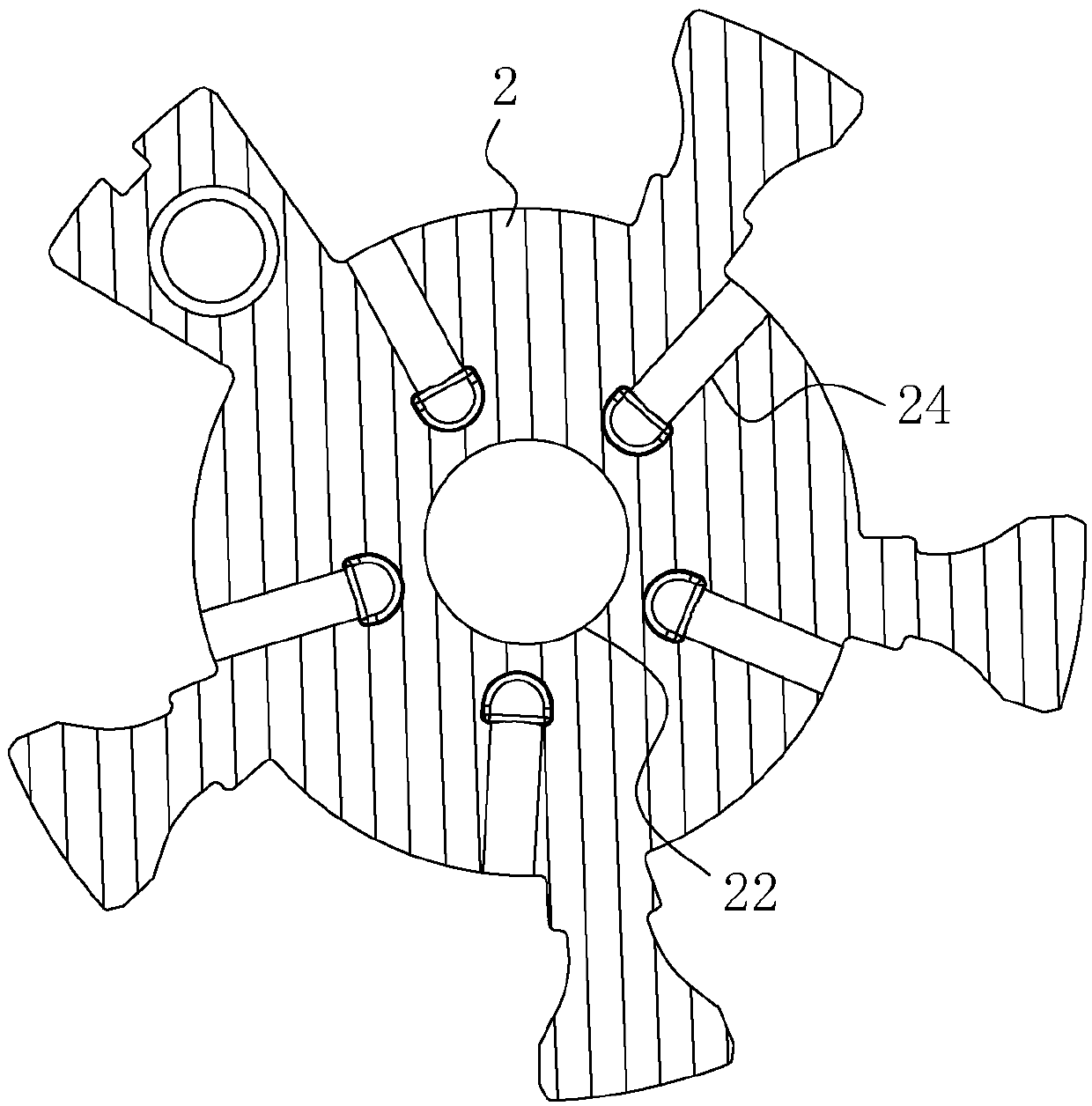
technical field [0001] The invention relates to the technical field of phase adjuster assembly, and more particularly, to a phase adjuster concentricity inflatable adjusting fixture and device. Background technique [0002] Engine variable camshaft phase adjuster (also known as phase shifter or VCP) is a necessary actuator for automobile engines to realize the variable valve timing VVT function. A certain phase change occurs in the crankshaft. [0003] The existing Chinese patent with the publication number of CN207634122U discloses a special-shaped sealed phase adjuster, which includes a circular stator, a rotor set inside the stator, a cover plate set on the front end surface of the stator, and a rear end surface of the stator. There are several bolt holes on the cover plate, stator, bottom plate and sprocket, which are connected and fixed as a whole by bolts passing through the bolt holes. [0004] Among them, refer to figure 1 and figure 2 , the stator 1 is provided...

Claims


Application Information

Patent Timeline
Patent Type & Authority Applications(China)
IPC IPC(8): B25B11/02B23P21/00
CPCB23P21/00B25B11/02
Inventor 曹仪锋
Owner HAILIDA AUTOMOBILE TECH CO LTD
Learn More