
Display device and method based on IO module and robot

A technology for a display device and a display control method, which is applied in the direction of electrical components, etc., can solve the problems of poor light guiding effect of LED lamps, etc., and achieve the effect of enhancing the light guiding effect, reducing the size, and reducing the size of the PCB

Active Publication Date: 2020-04-10
GREE ELECTRIC APPLIANCES INC
View PDF14 Cites 0 Cited by
  • Summary
  • Abstract
  • Description
  • Claims
  • Application Information

AI Technical Summary

Problems solved by technology

The present invention reduces the size of the single-board PCB through the structure and hardware design scheme of the LED lamp board, and solves the problem of poor light guide effect of more LED lamps in the case of an integrated structure

Method used


Image

  • Display device and method based on IO module and robot
  • Display device and method based on IO module and robot

Examples


Embodiment

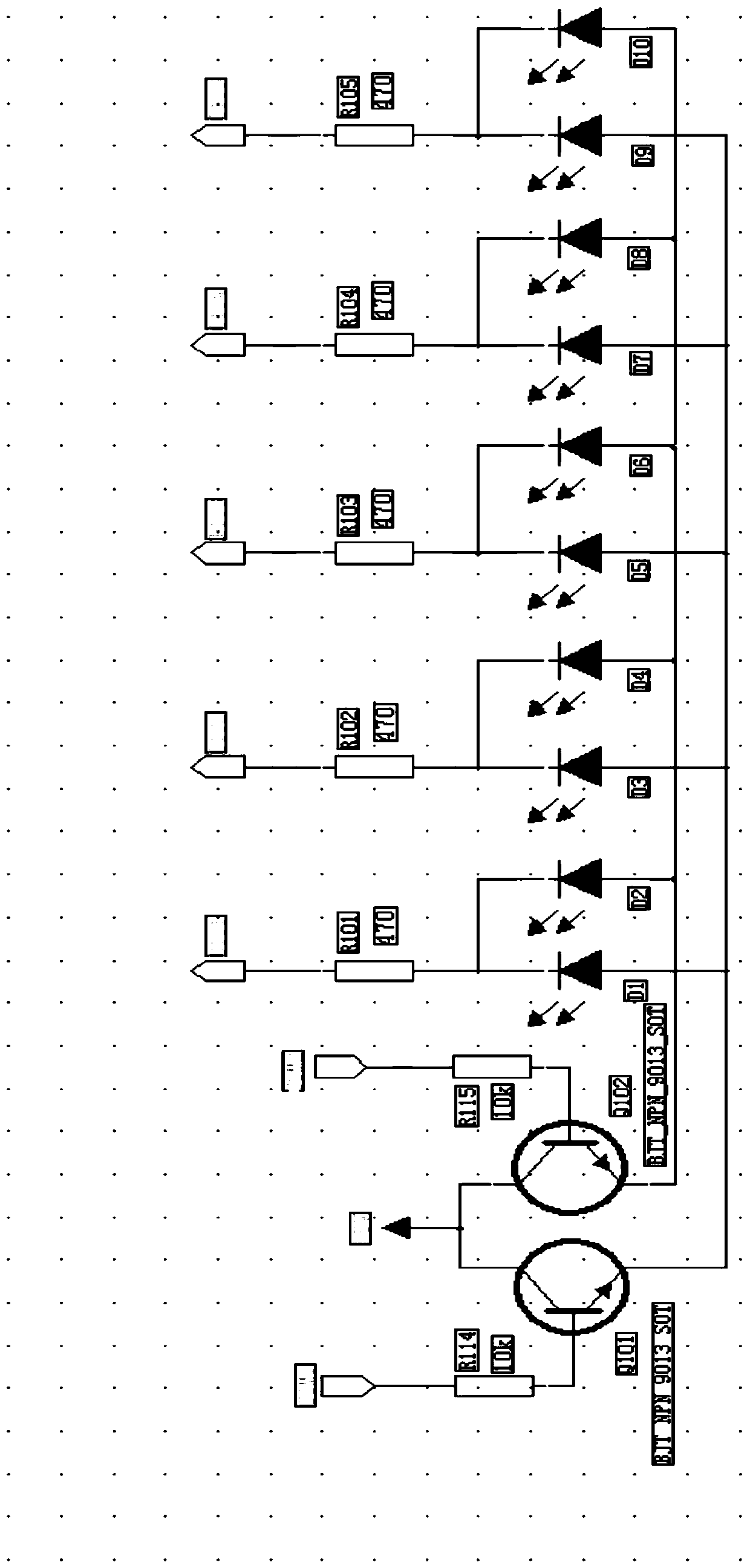
[0052] Such as figure 1 As shown, the LED light board 4 uses two transistors Q101 and Q102 to scan and drive 10 LED light assemblies 4 in time-sharing through the corresponding LED matrix scanning circuit. Whether the LED light assembly 4 is lit represents the on-off display status of each channel of the IO terminal 2 . The bases of the two Q101 and Q102 transistors are respectively connected to one I / O port, and 4 LED lamp components are connected to one I / O port in a group to form a 2×5 scanning circuit and realize 7 I / O ports The port controls 10 LED lamp components 4. When the number of LED lamp components 4 lights increases, the number of related devices can be increased in the same way. The I / O port of the LED lamp board outputs a high level of +5V, which can be adjusted by adjusting the current limiting resistor ( R101-R105) to adjust the brightness of the LED lamp assembly 4. D1-D10 in the LED lamp assembly 4 can adopt suitable patch light-emitting diodes or in-line ...


PUM


Abstract

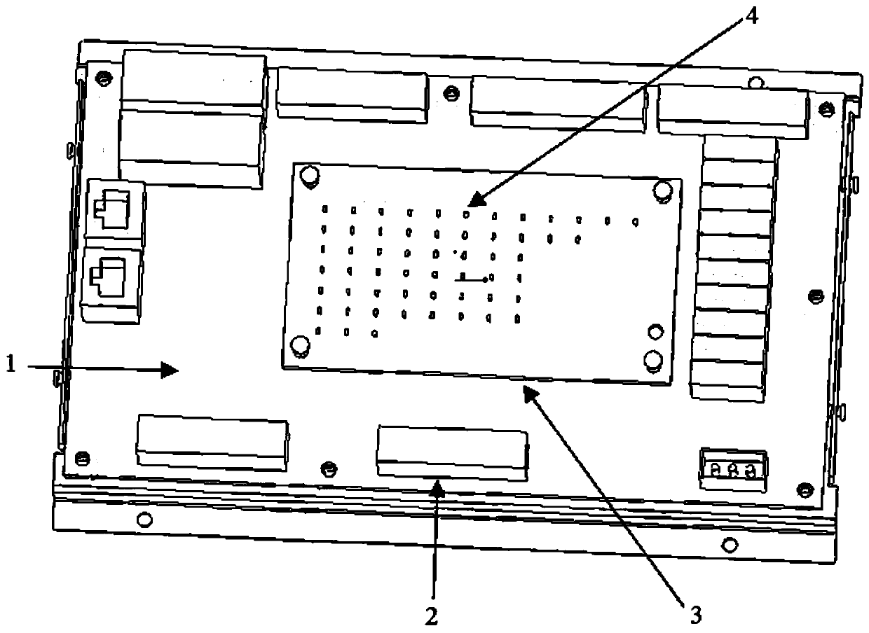
The invention belongs to the technical field of display systems, and discloses a display device and method based on an IO module and a robot, and the display device of the IO module of the robot is provided with LED lamp panels. The LED lamp panels are stacked above the main board in a longitudinal distribution mode and are connected with one another through flat cables; the LED lamp panels utilize an LED matrix scanning circuit to scan and drive a plurality of integrated LED lamp assemblies, and utilize whether the LED lamp assemblies are lightened or not to display the on-off display state of each loop when an IO terminal is connected to a load. The IO terminal is connected with the LED lamp panels through an IO port and is fixed on the main board. Through the adoption of the design scheme of the LED lamp panels, the size of the PCB is reduced in hardware, the difficulty in adding the design of a light guide column is structurally reduced, and a better light guide effect is achieved.Compared with a traditional PCB, the size is reduced by 20%, and the light guide effect is enhanced by 30%.

Description

technical field [0001] The invention belongs to the technical field of display systems, and in particular relates to a display device, method and robot based on an IO module. Background technique [0002] At present, the existing technology commonly used in the industry is as follows: each IO interface line of the robot controller IO module in the industry is required to have an LED light display, as a necessary method to indicate whether the IO of the IO is in normal communication. As long as the input and output terminals of all IO modules are connected with a complete load circuit, the LED lights on the line will be powered on and lit, and integration developers and customers can judge whether the IO line is connected normally and judge the connected IO channel. Whether there is a fault, and then efficiently find out the cause of the system communication detection alarm and other faults. [0003] However, usually for IO modules that do not require miniaturization and hav...

Claims


Application Information

Patent Timeline
IPC IPC(8): H05B45/30H05B45/50
Inventor 黄诚成胡飞鹏王长恺钟成堡
Owner GREE ELECTRIC APPLIANCES INC
Learn More