LED driving circuit

A technology of LED driving and load driving circuits, which is applied in the direction of lamp circuit layout, electric light sources, lighting devices, etc., and can solve the problems of increased PCB board size of LED driving circuit system, increased cost of LED power supply system, and complicated circuit system design. , to achieve the effect of improving power conversion efficiency, reducing PCB size and reducing cost

Inactive Publication Date: 2014-03-05
SUZHOU POWERLINK MICROELECTRONICS
View PDF3 Cites 15 Cited by
  • Summary
  • Abstract
  • Description
  • Claims
  • Application Information

AI Technical Summary

Problems solved by technology

[0004] The flyback switching circuit uses the auxiliary winding NA to detect the zero-crossing moment of the current of the diode D, and the feedback circuit needs to use components such as rectifier diodes and voltage divider resistors, which will complicate the design of the entire circuit system and make The PCB board size of the LED drive circuit system increases, which will increase the cost of the LED power supply system and limit its use.

Method used


Image

  • LED driving circuit
  • LED driving circuit
  • LED driving circuit

Examples


Embodiment Construction

[0023] Embodiments of the present invention are described below through specific examples, and those skilled in the art can easily understand other advantages and effects of the present invention from the content disclosed in this specification. The present invention can also be implemented or applied through other different specific implementation modes, and various modifications or changes can be made to the details in this specification based on different viewpoints and applications without departing from the spirit of the present invention.

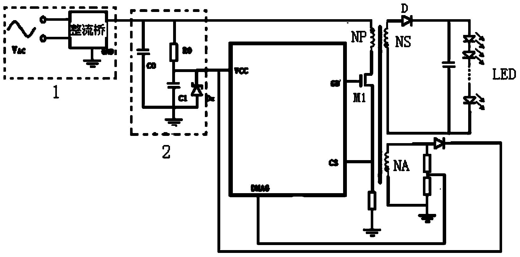
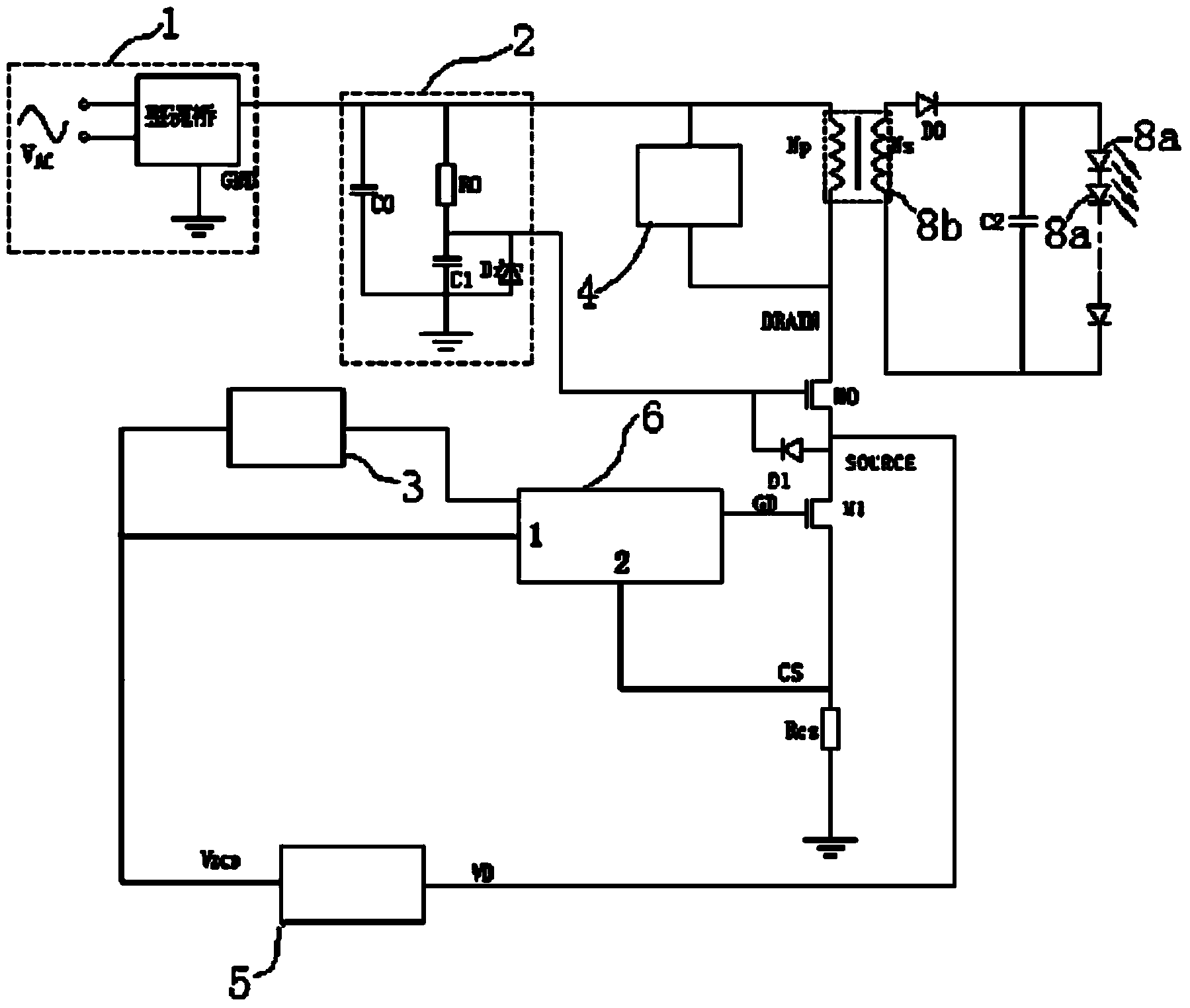
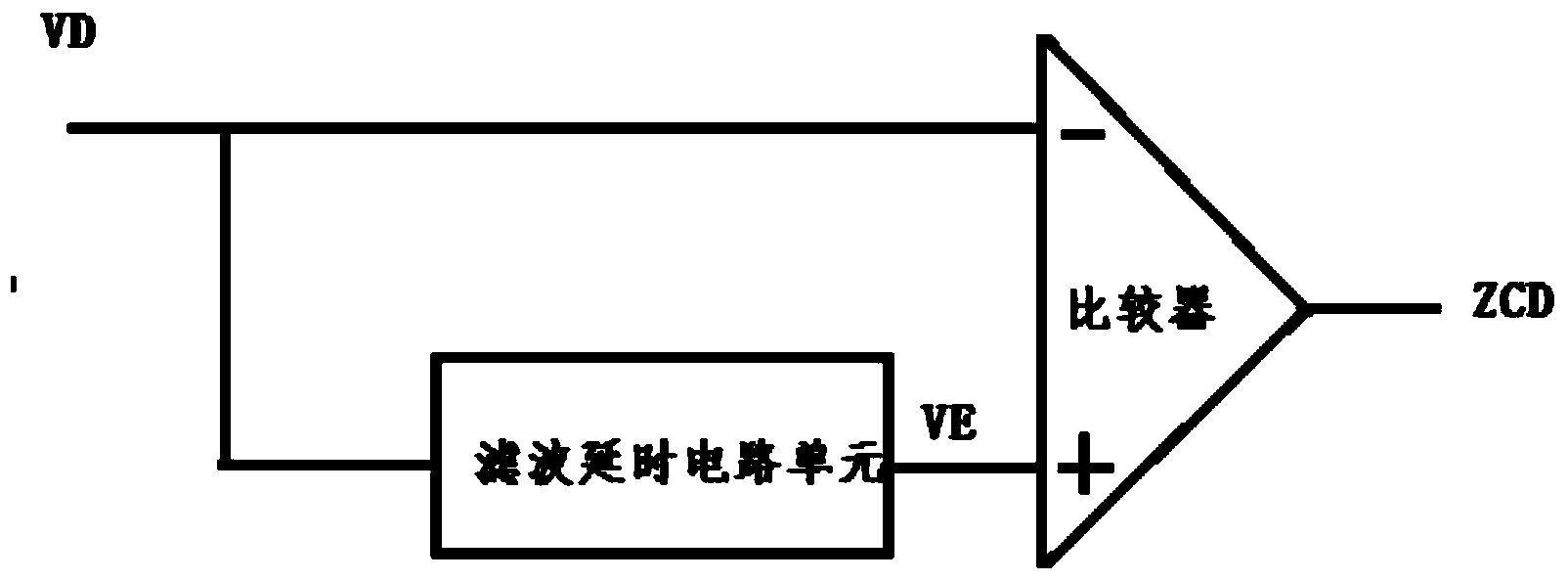
[0024] see Figure 2 to Figure 7 , It should be noted that the diagrams provided in this embodiment are only schematically illustrating the basic idea of ​​the present invention, and only the components related to the present invention are shown in the diagrams rather than the number and shape of components in actual implementation. and size drawing, the type, quantity and proportion of each component can be changed arbitrarily during...


PUM


Abstract

The invention provides an LED driving circuit. The LED driving circuit comprises a rectifying circuit, a power supplying circuit, a load driving circuit and a switch circuit. A zero-cross detecting unit of the switch circuit is used for detecting the source electrode voltage of a first power switch pipe to obtain the on-off time and the conduction time of a fly-wheel diode, and then LED constant current driving is achieved. According to the LED driving circuit, a driving power source can be simplified, the size of a PCB of the LED driving power source can be reduced, and the cost of an LED driving power application system is reduced; according to the driving circuit, the zero current time of the fly-wheel diode can be obtained with the only requirement for collecting the source electrode voltage of the first power switch pipe, and the design difficulty, the area and the cost of a chip can be reduced; when the driving circuit is in a BCM, the switch loss can be reduced, the power transfer efficiency is improved, and the EMI can be improved.

Description

technical field [0001] The invention relates to the field of circuit electronics and integrated circuits, in particular to a driving circuit for supplying power to LEDs. Background technique [0002] LED (Light Emitting Diode) is a semiconductor electronic component that can emit light. LED can only be turned on (energized) in one direction. When current flows, electrons and holes recombine in it to emit monochromatic light. Luminescence effect, and the wavelength and color of light are related to the type of semiconductor material used and the elemental impurities doped. It has the advantages of high efficiency, long life, not easy to break, high switching speed, high reliability, etc. that traditional light sources cannot match. Because LED has the advantages of energy saving and environmental protection, it is gradually popularized and used. At the same time, users have put forward higher and higher requirements for its performance, especially the cost control requiremen...

Claims


Application Information

Patent Timeline
Patent Type & Authority Applications(China)
IPC IPC(8): H05B37/02
Inventor 张永良佟国增万海军周海军韩兴成
Owner SUZHOU POWERLINK MICROELECTRONICS
Why Eureka
Try Eureka