Camshaft for a pump, in particular a high pressure fuel pump, and pump having a camshaft

一种凸轮轴、凸轮的技术,应用在轴和轴承、燃料喷射泵、凸轮等方向,能够解决凸轮滚子挺杆和滚子磨损等问题,达到磨损小的效果

Active Publication Date: 2020-04-10
ROBERT BOSCH GMBH
View PDF6 Cites 0 Cited by
  • Summary
  • Abstract
  • Description
  • Claims
  • Application Information

AI Technical Summary

Problems solved by technology

As a result, large loads occur when driving the pump piston, for example an inclined position between the roller tappet and the cam, which can lead to increased wear of the cam as well as the roller tappet and the rollers

Method used


Image

  • Camshaft for a pump, in particular a high pressure fuel pump, and pump having a camshaft
  • Camshaft for a pump, in particular a high pressure fuel pump, and pump having a camshaft
  • Camshaft for a pump, in particular a high pressure fuel pump, and pump having a camshaft

Examples


Embodiment Construction

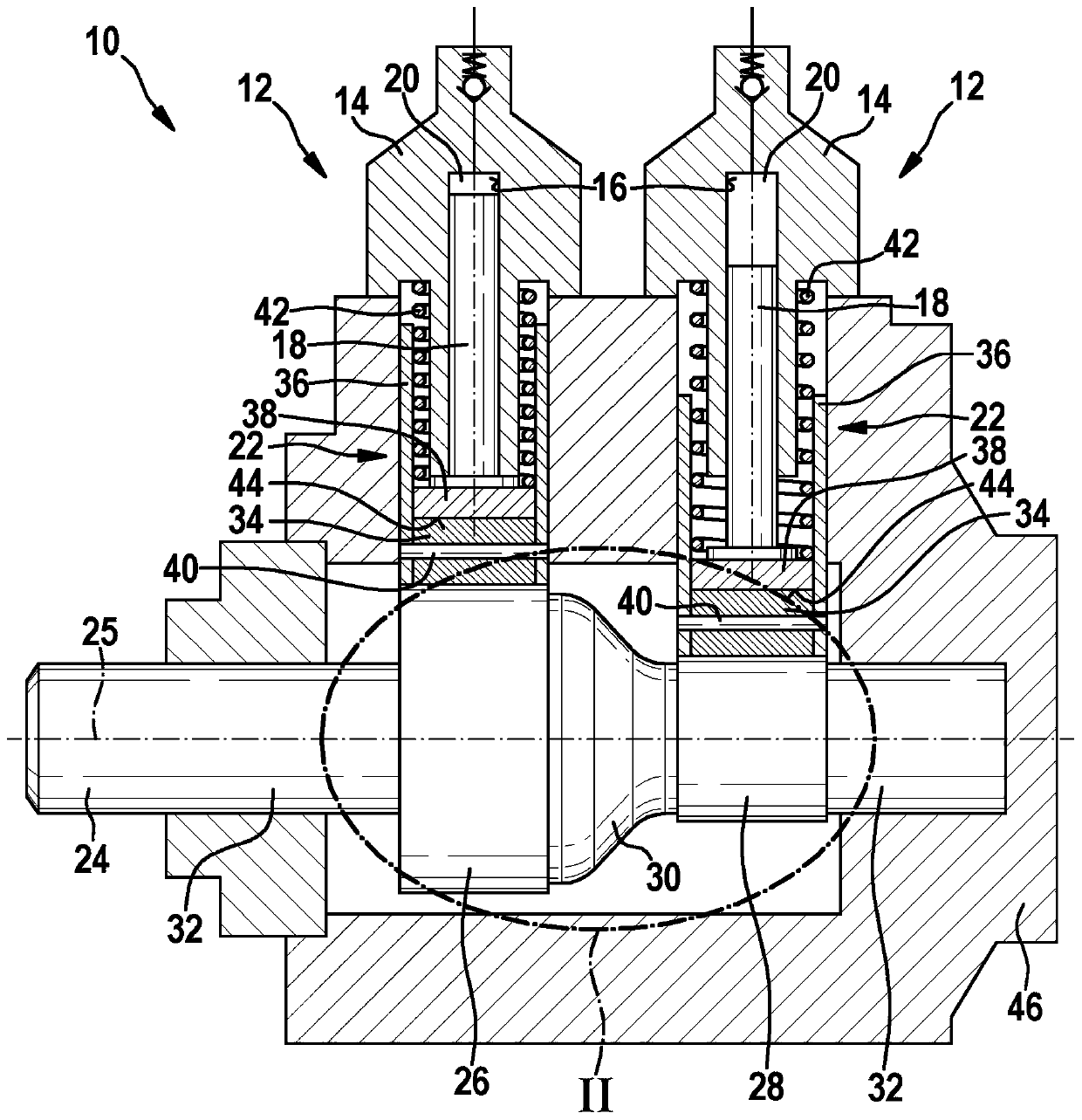
[0006] exist Figure 1 to Figure 6 In a simplified illustration, a pump 10 is shown, which is provided in particular for the high-pressure delivery of fuel in a fuel injection system of an internal combustion engine. The pump 10 has at least two pump elements 12 which each have a housing part 14 in which pump pistons 18 are each movably guided in a cylinder bore 16 which A pump working chamber 20 is delimited in the corresponding cylinder bore 16 . The pump pistons 18 are each driven via a tappet 22 by the camshaft 24 in a lifting motion in at least approximately radial direction relative to the rotational axis 25 of the camshaft 24 . The axis of rotation 25 of the camshaft 24 is coaxial with its longitudinal axis. The camshaft 24 can be part of the pump 10 , or alternatively it can also be provided that the pump 10 does not have its own camshaft and that the camshaft 24 is part of the internal combustion engine.

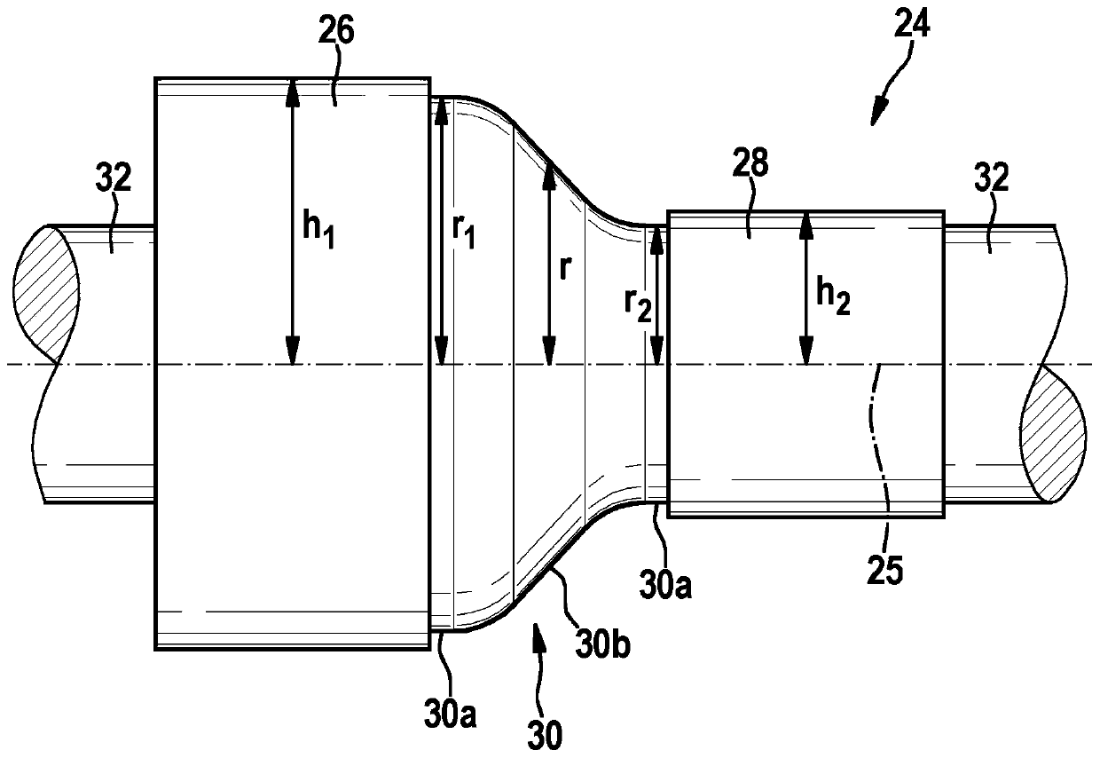
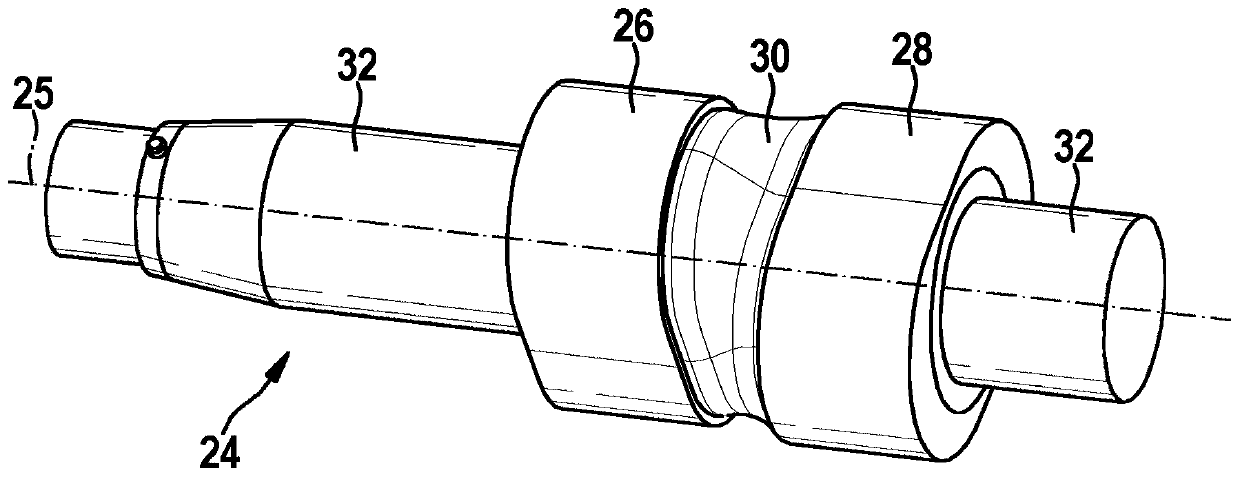
[0007] The camshaft 24 has two cams 26 , 28 arranged one be...


PUM


Abstract

A camshaft (24), in particular for a pump (10), is proposed. The camshaft (24) has at least two cams (26, 28) which are arranged next to one another in the direction of the longitudinal axis (25) of the camshaft (24) and the cam elevations of which are arranged offset with respect to one another around the longitudinal axis (25) of the camshaft (24). An intermediate region (30) is provided betweentwo adjacent cams (26, 28), and at least one bearing region (32) is arranged next to the cams (26, 28) in the direction of the longitudinal axis (25) of the camshaft (24). The intermediate region (30) runs in axial longitudinal sections which contain the longitudinal axis (25) of the camshaft (24), at a radial spacing (r1, r2) from the longitudinal axis (25) of the camshaft (24), which radial spacing (r1, r2), starting from the adjacent cam (26) with the smaller cam elevation (h1) in the respective axial longitudinal section, increases towards the adjacent cam (28) with the greater cam elevation (h2) in the respective axial longitudinal section.

Description

technical field [0001] The invention proceeds from a camshaft of the type according to claim 1 for a pump, in particular a high-pressure fuel pump, and from a pump of the type according to claim 7 with a camshaft. Background technique [0002] Such a camshaft and such a pump in the form of a high-pressure fuel pump are known from DE 10 2009 002 014 A1. The pump has two pump elements and a camshaft, the pump elements each having a pump piston, via which the pump pistons are each driven via a roller tappet in a lifting motion. The camshaft has two cams arranged one behind the other in the direction of its longitudinal axis, the cam lobes of which are arranged offset relative to one another around the longitudinal axis of the camshaft. The cam can be, for example, a 180° double cam and its cam projections are arranged offset or twisted by 90° relative to one another around the longitudinal axis of the camshaft. In addition to the cam, the camshaft has at least one bearing reg...

Claims


Application Information

Patent Timeline
Patent Type & Authority Applications(China)
IPC IPC(8): F04B1/0538F04B1/0413F02M59/06F16H53/02F04B9/04
CPCF04B1/0413F04B1/0538F04B9/042F16H53/025F16C3/02F16C2360/18F01L1/047F01L1/08F02M59/102F02M2200/03F02M2200/02B23P2700/02F02M59/06F02M59/44
Inventor M·伊姆霍夫R·迈尔
Owner ROBERT BOSCH GMBH
Why Eureka
Try Eureka