Cutting device of straightening cutting machine

A cutting device and cutting machine technology, applied in the field of mechanical shearing mechanism, can solve the problems of cutting knife damage, jumping, lack of limit mechanism, etc., and achieve the effect of improving quality and extending service life

Active Publication Date: 2020-04-14
嘉兴凯鑫五金科技股份有限公司
View PDF8 Cites 1 Cited by
  • Summary
  • Abstract
  • Description
  • Claims
  • Application Information

AI Technical Summary

Problems solved by technology

[0003] In the prior art, when the workpiece enters the cutting mechanism for cutting, it does not have a limit mechanism, or the limit mechanism is outside the cutting mechanism (ie, the guide wheel) and is far away from the cutting mechanism, resulting in the workpiece being cut. When the cutting part jumps, it affects the quality of cutting, and the cutting knife is easily damaged, resulting in frequent replacement of the cutting knife.

Method used


Image

  • Cutting device of straightening cutting machine
  • Cutting device of straightening cutting machine
  • Cutting device of straightening cutting machine

Examples


Embodiment Construction

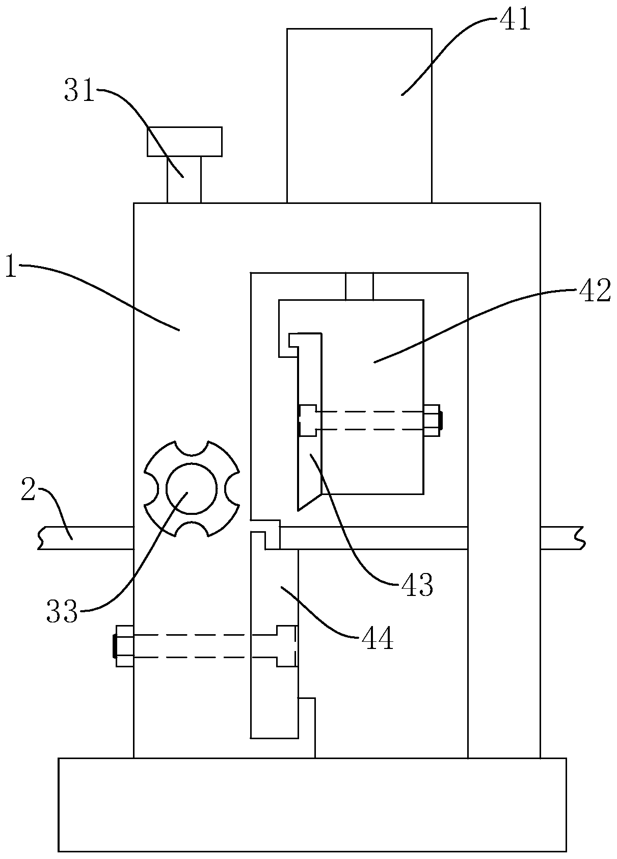
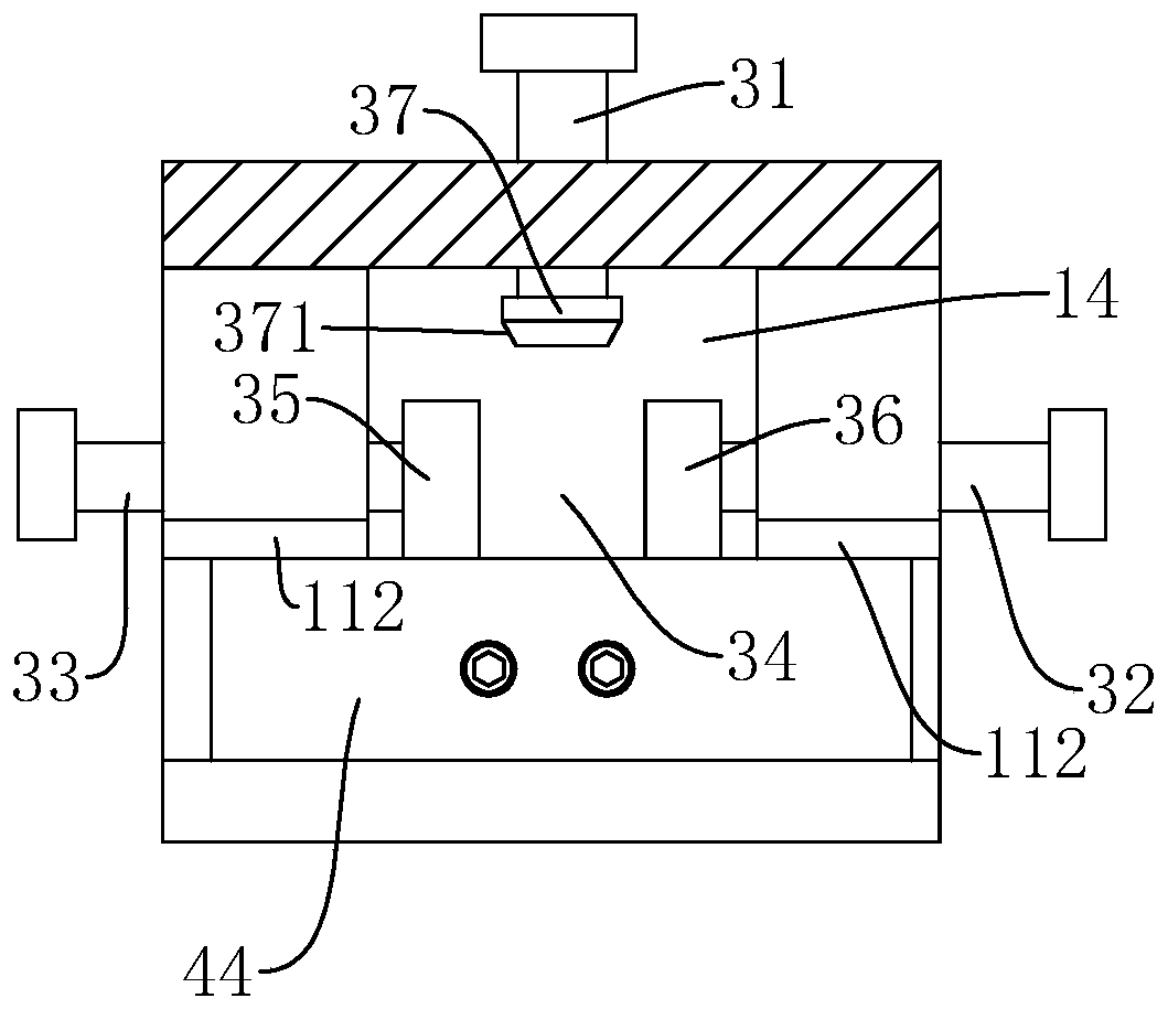
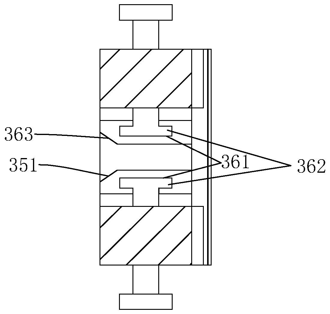
[0022] Combine Figure 1 to Figure 5 The cutting device of the straightening and cutting machine of the present invention will be further described.

[0023] A cutting device for a straightening and cutting machine is characterized in that it comprises a frame body 1, a workpiece limit mechanism, a fixed knife 44 and a movable knife mechanism.

[0024] The frame body 1 includes a top plate 12, a vertical plate 11 and a supporting column 13 located on the left and right sides of the top plate 12, and the vertical plate 11 has a workpiece channel 14 thereon.

[0025] The workpiece limit mechanism includes a left adjustment rod 32, a right adjustment rod 33, and an upper adjustment rod 31; the left adjustment rod 32, the right adjustment rod 33, and the upper adjustment rod 31 are screwed to the left side wall of the workpiece channel 14, respectively, The first ends of the right side wall and the top wall, as well as the left adjustment rod 32, the right adjustment rod 33 and the uppe...


PUM


Abstract

The invention discloses a cutting device of a straightening cutting machine. The cutting device is characterized by comprising a frame body, a workpiece limiting mechanism, a fixed cutter and a movable cutter mechanism, wherein the frame body comprises a vertical plate and a top plate, a workpiece channel is formed on the vertical plate, the workpiece limiting mechanism comprises a left adjustingrod, a right adjusting rod and an upper adjusting rod, the left adjusting rod, the right adjusting rod and the upper adjusting rod are in threaded fit with a left side wall, a right side wall and a top wall of the workpiece channel correspondingly, first ends of the left adjusting rod, the right adjusting rod and the upper adjusting rod are all located in the workpiece channel and form a limitingchannel, the fixed cutter is installed on a back face of the vertical plate, a cutting edge of the fixed cutter and a low point of the limiting channel are located on the same horizontal line, the movable cutter mechanism comprises a movable cutter and an oil cylinder, and the oil cylinder is installed on the top plate and connected with the movable cutter so as to drive the movable cutter to moverelative to the fixed cutter. The cutting device is advantaged in that the cutting quality of a workpiece can be improved, the service life of the cutting knife can be prolonged, and a replacement period of the cutting knife is shortened.

Description

Technical field [0001] The invention relates to a mechanical shearing mechanism, and more particularly to a cutting device of a straightening and cutting machine. Background technique [0002] When metal wire is produced, it is necessary to reel the wire into a coil for storage and transportation. However, when the wire is used, it is often necessary to straighten the wire and cut it into an equal length. At present, the straightening machine is mainly used to straighten the steel bar, and the straightened steel bar is cut by a cutting mechanism. [0003] In the prior art, when the workpiece enters the cutting mechanism for cutting, it does not have a limiting mechanism, or the limiting mechanism is outside the cutting mechanism (that is, the guide wheel) and is far away from the cutting mechanism, resulting in the workpiece being cut At this time, the part to be cut has a problem of jumping, which affects the quality of the cutting, and the cutting knife is easily damaged, causin...

Claims


Application Information

Patent Timeline
Patent Type & Authority Applications(China)
IPC IPC(8): B21F1/02B21F11/00B21F23/00
CPCB21F1/026B21F11/00B21F23/00
Inventor 吴新祥
Owner 嘉兴凯鑫五金科技股份有限公司
Why Eureka
Try Eureka