High-temperature spiral feeder

A screw feeder and high-temperature technology, which is applied in the field of material conveying equipment, can solve the problems of wasting water resources, complex water seal of the rotating shaft, and high operating costs, and achieve energy saving, simple and compact overall structure, and low operating costs.

Pending Publication Date: 2020-04-14
洛阳炬星窑炉有限公司
View PDF0 Cites 1 Cited by
  • Summary
  • Abstract
  • Description
  • Claims
  • Application Information

AI Technical Summary

Problems solved by technology

Although this structure is compact, the water seal of the rotating shaft at high temperature is relatively complicated, and it needs to continuously add water for cooling, which wastes water resources and high operating costs.

Method used


Image

  • High-temperature spiral feeder
  • High-temperature spiral feeder
  • High-temperature spiral feeder

Examples


Embodiment Construction

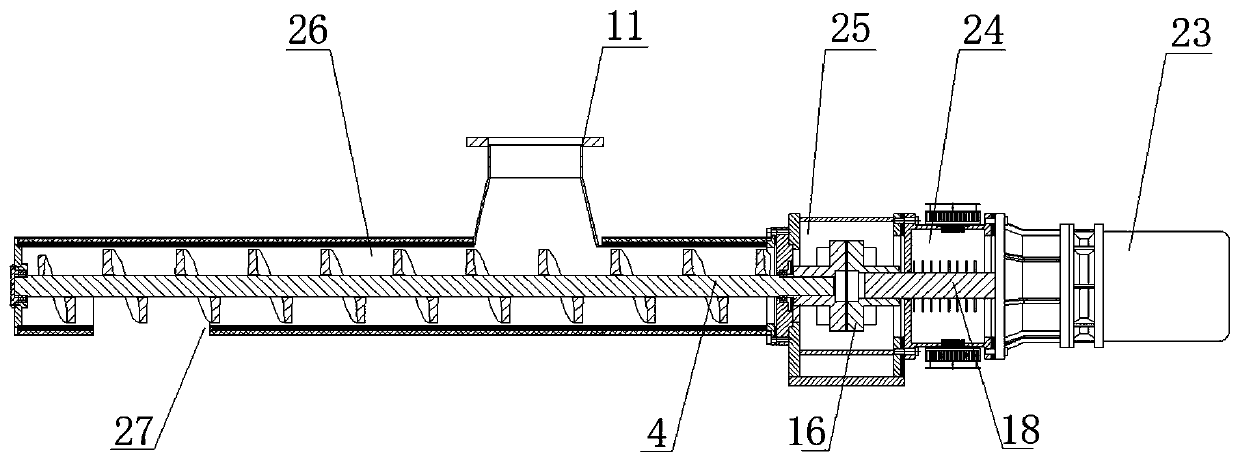
[0020] Such as figure 1 As shown, a high-temperature screw feeder of the present invention includes a motor reducer 23 , a cooling section 24 , a heat insulation section 25 and a high-temperature feeding section 26 connected in sequence from left to right. The output shaft 18 of the motor reducer 23 passes through the cooling section 24 and then connects with the auger main shaft 4 in the high temperature feeding section 26 through the coupling 16 in the heat insulation section 25 .

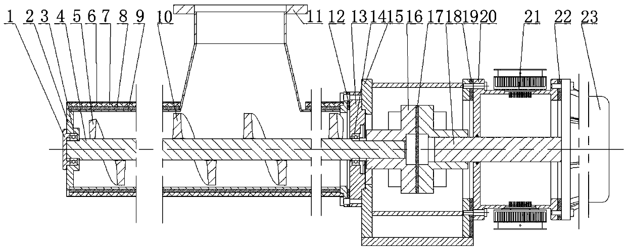
[0021] combine figure 2 Shown:

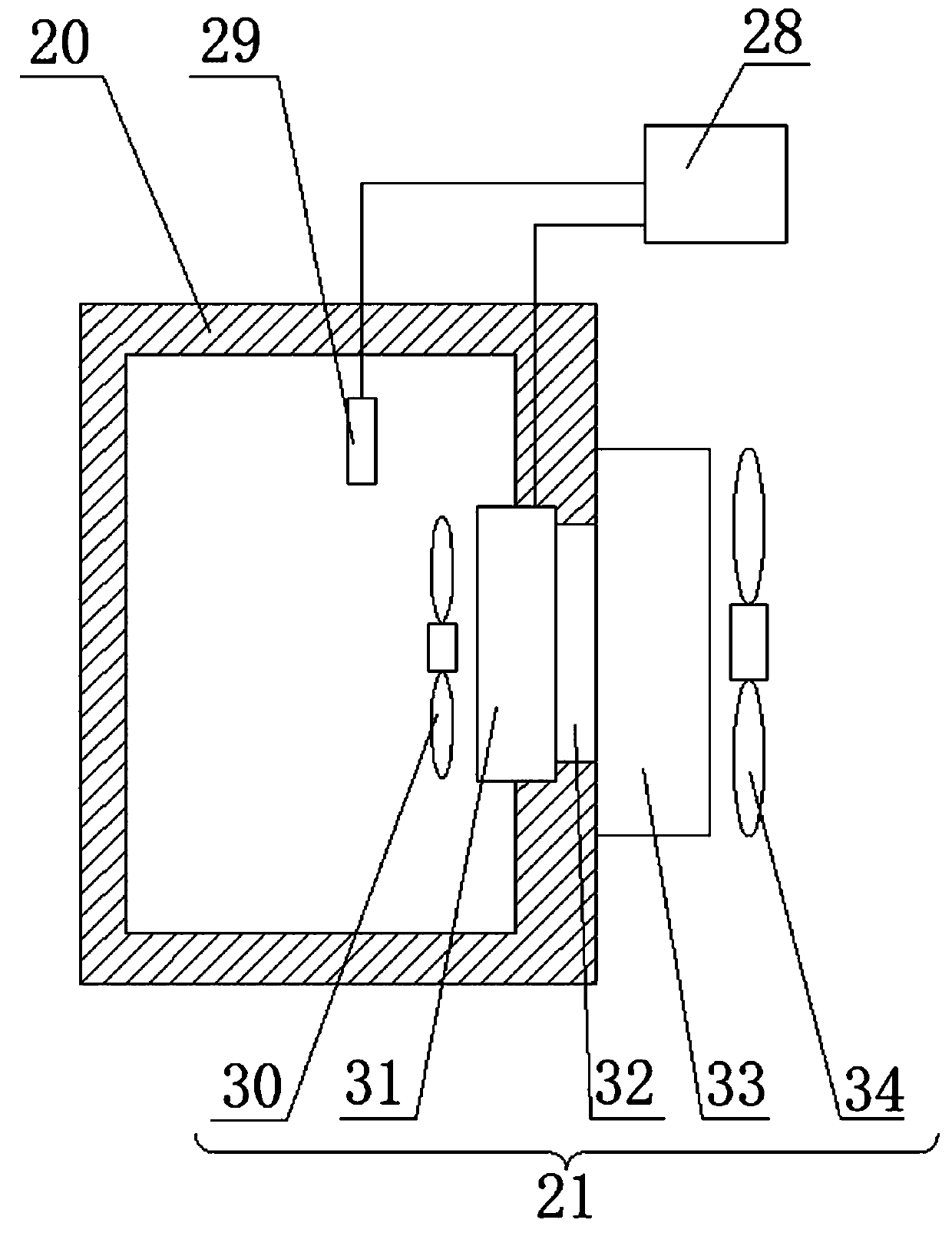
[0022] The main function of the cooling section 24 is to absorb the heat transferred from the high-temperature feeding section 26 through the heat insulation section 25 by means of refrigeration, and to control the temperature of the cooling section 24 and the output shaft 18 at about room temperature. The cooling section 24 includes a cooling box 20, a temperature sensor 29 arranged in the inner cavity of the cooling box 20, a semiconductor refrigerator 21 arr...


PUM


Abstract

The invention relates to the field of material conveying equipment, specifically a high-temperature spiral feeder. The high-temperature spiral feeder comprises a motor reducer, a cooling section, a heat insulation section and a high temperature feeding section which are connected in sequence, wherein the output shaft of the motor reducer penetrates the cooling section and then is connected to a spiral conveyer main shaft in the high temperature feeding section through a shaft coupling in the heat insulation section; the cooling section comprises a cooling box, a temperature sensor arranged inthe inner cavity of the cooling box, a semiconductor cooler arranged on the wall of the cooling box, and a temperature controller arranged outside the cooling box; a first heat insulation gasket is clamped between the cooling box and the motor reducer; a second heat insulation gasket is clamped between the cooling box and the heat insulation section; the signal output of the temperature sensor isconnected to the temperature controller, and the signal output of the temperature controller is connected to the semiconductor cooler; and the on-off of the semiconductor cooler can be controlled by the temperature controller through the temperature signal measured by the temperature sensor. The high-temperature spiral feeder has a compact structure, does not require water cooling, and can guarantee the continuous transportation of high temperature materials.

Description

technical field [0001] The invention relates to the field of material conveying equipment, in particular to a high-temperature screw feeder. Background technique [0002] In industrial production, high-temperature screw feeders are needed to transfer high-temperature materials between heating furnaces or between heating furnaces and external production lines. In order to ensure normal operation at high temperature, the feeding section of the high-temperature screw feeder often uses high-temperature-resistant materials and bearings, but the motor reducer that drives the auger to rotate and feed cannot meet the high-temperature-resistant requirements. Some high-temperature screw feeders separate the motor and reducer from the feeding section, and drive the rotation of the screw auger through a chain or gear. Such a structure will cause the volume of the whole high-temperature screw feeder to be large and the transmission to be unstable. There are also some high-temperature s...

Claims


Application Information

Patent Timeline
Patent Type & Authority Applications(China)
IPC IPC(8): B65G33/24B65G33/26B65G33/32B65G33/34B65G69/20
CPCB65G33/24B65G33/265B65G33/32B65G33/34B65G69/20
Inventor 王国庆
Owner 洛阳炬星窑炉有限公司
Why Eureka
Try Eureka